
Galvin Power is reader-supported. When you buy via our links, we may earn a commission at no cost to you. Learn more

How to Wire a Shunt Trip Breaker Wiring Diagram (DIY Guide)
Written by Edwin Jones / Fact checked by Andrew Wright
Table of Contents
Tools You Need
Step 1. install shunt trip accessory to the circuit breaker, step 2. installing shunt trip circuit breaker to the panel board, step 3. understanding the shunt trip breaker wiring diagram, step 4. start wiring the shunt trip circuit breaker to the safety control, step 5. checking or testing the installed unit.
Do you want to have an additional layer of protection for your home? Are you planning to install a shunt trip breaker in your home circuit? Are you looking for a how to wire a shunt trip breaker wiring diagram?
Yes, shunt trip breakers protect your home by cutting off power when activated manually or by your sensor. Although it’s not required, it ensures that power is switched off when the sensor is triggered. These sensors could be smoke detectors, fire alarms, or even a manual emergency stop button.
If you intend to add a safety system, I highly recommend reading through the steps below to know what to expect when installing this accessory.
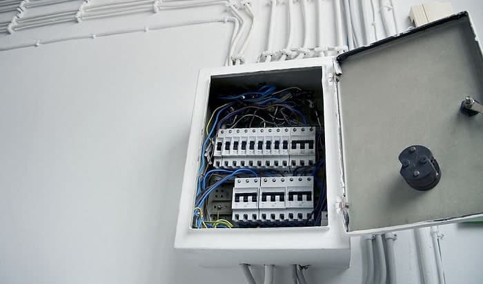
These are the tools and items you need to get started:
- Shunt trip accessory designed for your existing circuit breaker model .
- A circuit breaker is compatible with your shunt trip accessory if your current breaker isn’t compatible with any shunt trip accessories.
- An emergency stop switch if you want to install a kill-switch button.
- Screwdrivers of various tips and sizes as required in your electrical system
- A Shunt trip wiring diagram as your wiring guide
- Insulating gloves and eye protection
Not all circuit breakers accept shunt trip accessories. In fact, different breakers may require specific shunt trip accessory models. Some breakers also have a built-in shunt trip accessory—all you need is to wire and connect to your circuit to activate it.
Furthermore, some circuit breakers are only intended to have shunt trip accessories installed from the factory. So, before purchasing a shunt trip accessory, it’s highly recommended that you review what make and model of breaker you have. That way, you know what your options are before installation.
If you have a compatible system, you still need a shunt trip circuit breaker wiring diagram to ensure correct installation. However, do not just download any chart from the internet. For example, if you have a Square D branded circuit breaker, you need a Square D shunt trip breaker wiring diagram.
Before beginning installation, ensure that everything you need is within your reach. Also, always think of safety first!
Step-By-Step Guide to Wire a Shunt Trip Breaker Wiring Diagram

First, install the shunt trip accessory to your breaker. This procedure is pretty straightforward. Open your circuit breaker using a small flathead screw. Insert the insulator into its right place, and feed the wires in the holes near the shunt trip. Secure the shunt trip to its location, and put the cover back to the circuit breaker. And you’re done!
You can watch this video by Aaron CBIONE for a video guide on installing a shunt trip to the circuit breaker.
Note: Different makers have different installation processes. It’s best to refer to the manual guide provided in your circuit breaker.
Once the shunt trip accessory is connected to your circuit breaker, you need to connect it to your panel board as the main circuit breaker. Before installing this device, ensure that your system has no power.
If you’re not sure, it’s best to consult a professional electrician to avoid any accidents.
Once ready, open your panel board using your flathead screwdriver and plug in your shunt trip circuit breaker into the main power supply. Connect the mainline and the supply wire to the circuit breaker, then proceed to the next step.
Before wiring your shunt trip breaker to your safety control system or switch, you need first to understand its wiring diagram. This is a crucial part of the installation—that’s why you can’t skip it and need to be more careful with it.
Take a look at this recognizable wiring diagram made by Sikandar Haidar of Electriconline4u as a typical example.
Note: This sample diagram is simple and easy to follow. However, different systems may require other designs. Refer to the charts provided with the shunt trip, safety control system, or switch before starting. If you’re unsure, it’s best to consult a professional.
Using the sample above, connect one wire of the shunt trip to the neutral connection, then attach the other wire to the kill switch. Place a wire on the other side of the terminal of the kill switch through the supply connection.
With this, you now have a kill switch you can use to trip your electrical system’s main breaker quickly.
Pro Tip: Place the kill switch in an accessible area like near an emergency exit, so if a problem occurs, you can easily access it.
After installation, turn on or reconnect the power source to your main breaker panel . Flip the shunt trip circuit breaker on to begin testing your work.
To test your installation, press the kill switch. The shunt trip circuit breaker should immediately trip after pressing the kill switch. If it is not tripped, then there is something wrong with your installation.
Although not a requirement, having a shunt trip breaker in your residence provides an additional layer of safety. This is an excellent option if you have sensors in your building, like smoke detectors or fire alarms.
In case of emergencies, like flooding or sprinkler activation, you can also cut the power source by hitting the kill switch. This can prevent any shorts or accidental electrocutions because no power is supplied to your outlets.
So, what do you think of the installation process? Is it easy enough to DIY? Would you do this on your own? Remember to follow how to wire a shunt trip breaker wiring diagram. If you have any questions, feel free to reach out in the comments below.

I am Andrew Wright. With 8 years of experience designing, installing, and maintaining electrical power systems. I love my job, and I have always wanted to offer others the necessary help so they can take care of their houses.

Wire A Shunt Trip Breaker: Your Step-by-step Visual Guide
In the world of electrical engineering , dances with complex equipment are common. Few dances are as intricate as the one with the shunt trip breaker. As seasoned professionals, we guide you through this delicate ballet, ensuring your safety and the seamless operation of your electrical system.
Our comprehensive visual guide will demystify shunt trip breaker wiring, breaking down the process into manageable steps. By the end of this journey, you’ll possess the knowledge and skills to wire a shunt trip breaker with confidence.
First, let’s explore what a shunt trip breaker is and why it’s a crucial component in an electrical system.
Key Takeaways
- Shunt trip breakers are crucial in industrial settings and high-risk areas to prevent electrical fires and other hazards.
- The wiring diagram of a shunt trip breaker allows it to receive a signal from a separate source for immediate shutdown.
- The key parts of a shunt trip breaker include the coil, breaker mechanism, and trip unit, which work together to cut off power in case of overloads or faults.
- Proper installation and regular maintenance of shunt trip breakers are essential for ensuring system safety and efficiency.
Understanding the Importance and Functionality of Shunt Trip Circuit Breakers
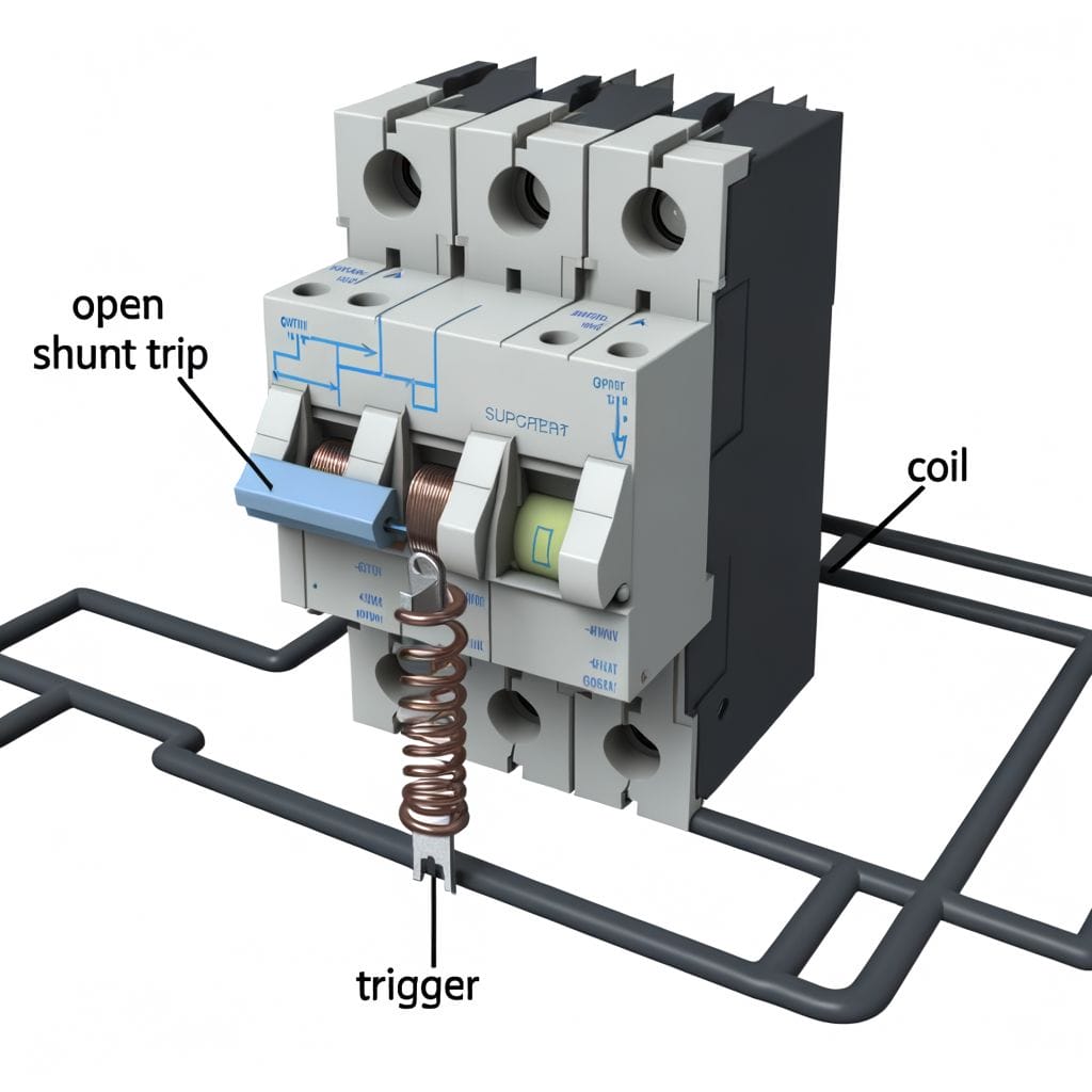
Diving into the heart of our discussion, it’s crucial to understand just what a Shunt Trip Circuit Breaker is. This innovative device shuts off an electrical circuit when it detects a problem, such as an overload or short circuit . This proactive functionality greatly reduces the risk of electrical fires and other potential hazards.
Its unique design allows the breaker to receive a signal from a separate source that triggers an immediate shutdown when necessary. This feature is particularly beneficial in environments where immediate circuit disconnection is paramount, like in industrial settings or high-risk areas.
Precision is key when installing a shunt trip breaker. A wrongly connected wire can compromise the breaker’s functionality, possibly leading to a dangerous situation. So, we strongly recommend professional installation to ensure the safety and efficiency of your electrical system.
Learning the Basics: Diagrammatic Representation of a Shunt Trip Breaker
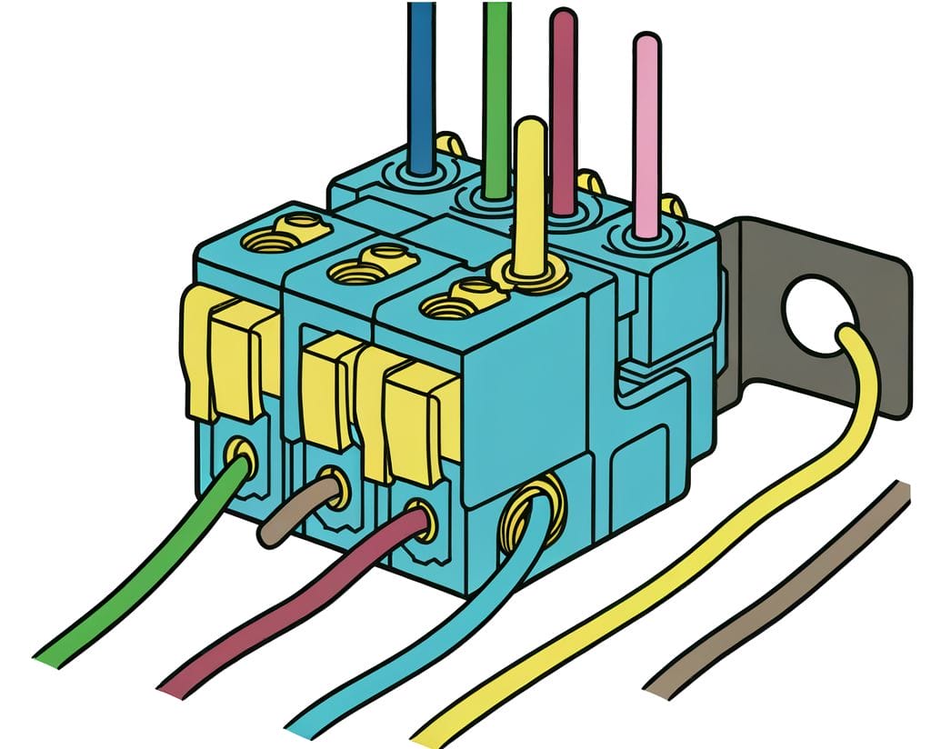
To grasp the workings of a shunt trip breaker, let’s delve into its diagrammatic representation. A shunt trip breaker is comprised of key parts like the coil, the breaker mechanism, and the trip unit. These parts work together to safely distribute electricity and prevent dangerous overloads.
The current first enters through the coil. When an electrical fault is detected, the coil becomes energized, triggering the trip unit. This in turn activates the breaker mechanism, causing the breaker to trip and cut off the power. It’s a simple and efficient system and serves as an innovative solution for electrical safety.
Detailed Steps to Wire a Shunt Trip Breaker Safely and Efficiently

Ready to wire a shunt trip breaker ? Start by preparing your workspace. Clear the area of any debris and make sure you have good lighting . Assemble your tools, which include a screwdriver, wire stripper, and multimeter.
Once your workspace is ready, follow the step-by-step process. Start by turning off the main power supply. After that, connect the shunt trip breaker to the circuit. Be sure to connect the wires correctly: the black wire to the breaker terminal, the white neutral wire to the neutral bus bar, and the green or bare ground wire to the ground bus bar.
Avoid common pitfalls like loose connections and incorrect wiring. Always double-check your work to ensure everything is wired correctly.
Connecting the Shunt Trip: An Essential Accessory for System Safety

A functioning shunt trip breaker represents an innovative approach to electrical safety. It automatically cuts power in the event of an electrical anomaly, shielding your system from damage. Hence, the importance of connecting the shunt trip can’t be overstated.
To wire a shunt trip breaker, we must employ a methodical approach. Connect the shunt trip coil to the breaker’s auxiliary terminal. Secure the connection using the recommended fasteners. Always test the shunt trip breaker to ensure it operates correctly and inspect the connection regularly for ongoing safety.
Troubleshooting Tips: Ensuring a Reliable Shunt Trip Breaker Connection
Even with careful installation, occasional challenges may arise in the wiring of a shunt trip breaker. To empower you further, let’s delve into troubleshooting tips for maintaining a reliable connection.
- Faulty Connections : If the shunt trip breaker isn’t functioning as expected, inspect the connections thoroughly. Ensure they are tight and secure. Reconnect any loose wires and tighten screws appropriately.
- Testing Procedures : Regularly test the shunt trip breaker using the recommended testing procedures. If the breaker fails to trip during a test, reassess the wiring and consult the manufacturer’s guidelines for troubleshooting.
- Voltage Issues : Check the voltage supply to the shunt trip breaker. Ensure it aligns with the specified requirements. Any discrepancies may affect the breaker’s performance. Consult a professional if voltage-related concerns persist .
- Visual Inspection : Periodically inspect the breaker for signs of wear, damage, or overheating. Replace any damaged components promptly. Visual cues can provide early warnings of potential issues.
- Interference and Environmental Factors : Assess the surrounding environment for potential interferences, such as electromagnetic interference or extreme temperatures. Shield the breaker from external factors that could compromise its functionality.
By familiarizing yourself with these troubleshooting techniques, you can address issues promptly, ensuring a reliable and efficient shunt trip breaker connection. Remember, a well-maintained breaker contributes significantly to the overall safety and reliability of your electrical system.
Are the Wiring Steps for a Shunt Trip Breaker Similar to a Water Well Pressure Switch?
No, the wiring steps for a shunt trip breaker are not similar to a water well pressure switch. While both involve wiring, the purpose and functionality of each are different. In the case of a shunt trip breaker, the wiring process will be specific to its functionality and requirements, and would not be interchangeable with water well pressure switch wiring .
In wrapping up, we’ve guided you through the crucial steps of wiring a shunt trip breaker. We trust you now understand its importance and how it operates.
With safety as our primary concern, we’ve shown you the right way to connect the shunt trip. Remember, knowledge is power, and this guide arms you with the needed expertise.
Keep exploring our guides for more practical electrical tutorials. Your safety and satisfaction are our top priorities.
Frequently Asked Questions
What is a shunt trip breaker.
A shunt trip breaker is a type of circuit breaker that can be triggered remotely to trip the breaker. It is frequently used in commercial kitchens, elevators, and other applications where the breaker needs to be tripped manually or remotely in case of an emergency.
Can you explain the shunt trip breaker wiring diagram?
The shunt trip breaker wiring diagram shows the connections for the shunt trip terminals, control circuit, and external power source. It also illustrates how the breaker is typically wired to trip the circuit breaker remotely or automatically during a surge or in case of an emergency such as a smoke alarm.
What is the purpose of a shunt trip breaker?
The main purpose of a shunt trip breaker is to provide circuit protection and to trip the breaker remotely or automatically during a surge, alarm, or emergency situation. It can help minimize equipment damage and ensure the safety of the electrical system.
How does a shunt trip breaker work?
A shunt trip breaker works by using an electromagnet to trip the breaker when it receives a signal from the control circuit. This can be done manually, through a relay, or remotely depending on the particular shunt trip accessories and model of the breaker.
What are the components of a shunt trip breaker?
A shunt trip breaker includes the main circuit breaker, shunt trip terminals, external power source, control system, and the shunt trip accessories. These components work together to trip the breaker manually or remotely in case of an emergency.
Similar Posts

How to Connect Two LED Strips Without Connectors: DIY Guide
How can you connect two LED strips without using connectors? Our DIY guide provides simple steps for seamlessly…
What Are Boat Risers: Your Comprehensive Riser Guide
A chain is only as strong as its weakest link. In the realm of marine engines, this link…

How Many Watts Is A Car Battery: The Power Behind Your Ride
Gaining an understanding of the battery of a car’s energy capabilities is essential for optimal performance and to…

How Long Can You Leave a Lava Lamp On All the Time?
Once a groovy relic from the 60s, my lava lamp adorns my bedside table. Its mesmerizing flow intrigues…

Can Alexa Be a Night Light? Amazon Echo as a Night Light
Many may question the practicality of using Alexa as a night light. However, we’ve discovered a surprising way…

Solar Power Developments: Solar Technology Advancements 2024
In 2024, solar technology is advancing rapidly. Solar cells have become more efficient, converting sunlight to electricity better…

Hassan Goodman
- DOWNLOAD THEME
worksheets in filipino for kindergarten download them and try to - download filipino worksheet for kindergarten 2 pics | kindergarten filipino worksheets pdf
One of the leading ways to find complimentary and high-quality kindergarten filipino worksheets pdf downloads is to start by searching online. The internet is home to a wide variety of websites that offer free kindergarten filipino worksheets pdf downloads, among other things templates, coloring pages, and more.
One methods to find these webpage is to use a search engine, such as Google or Bing, and enter proper keywords, such as "free kindergarten filipino worksheets pdf downloads" or "free kindergarten filipino worksheets pdf templates." This will educate a list of websites that offer free downloads, along with blogs, online stores, and even government websites.
Finding free download kindergarten filipino worksheets pdf can be obvious and accessible, you can use the search engine and visit websites that specialize in offering free stuff. Be choosy about the websites you visit, choose prominent sites that offer high-quality, accurate downloads.
worksheets in filipino for kindergarten download them and try to - download filipino worksheet for kindergarten 2 pics | kindergarten filipino worksheets pdf .

Related Posts
Posting komentar.
- Introduction to Masterpact MTZ Devices
- Masterpact MTZ Circuit Breaker Overview
- Selecting Masterpact MTZ1 Circuit Breakers
- Selecting Masterpact MTZ2 Circuit Breakers
- Selecting Masterpact MTZ3 Circuit Breakers
- Selecting Masterpact MTZ1 Switches
- Selecting Masterpact MTZ2 Switches
- Selecting Masterpact MTZ3 Switches
- Layout of the Micrologic X Control Unit
- Micrologic X Control Unit Protection Functions
- Long-Time Overload Protection (ANSI 49RMS/51)
- Short-Time Short Circuit Protection (ANSI 50TD/51)
- Instantaneous Short Circuit Protection (ANSI 50)
- Ground-Fault Protection (ANSI 50N-TD/51N)
- Protective Function Ratings
- Neutral Overload Protection on Four-Pole Circuit Breakers
- Trip Coil Supervision (ANSI 74)
- Lock-Out Function (ANSI 86)
- Overcurrent Trip Indication (ANSI 94)
- Dual Settings
- Overcurrent and Trip Cause Indications
- Trip History
- Protection Settings and Checking
- Setting Change Traceability
- Setting Change Locking
- Zone-Selective Interlocking (ZSI)
- ZSI Interface Module (ANSI 78)
- Instantaneous Override Protection and Close and Latch Ratings
- Measurements and Electrical Parameters Calculated by the Control Unit
- Energy Management Functions of Micrologic X Control Unit
- Effect of Temperature on Masterpact MTZ Circuit Breaker Measurement
- Micrologic X Control Unit Measurement Values
- Prevention of Power Supply Interruptions
- Restart After a Trip
- Warning and Alarm Displays
- Power Shutdown Prevention and Repair
- Prevent Power Shutdown with Conditional Checks
- Repairing a Device
- Event Logbooks
- Event Notification
- Event Type and Reset Mode
- Micrologic X Control Unit Voltage Measurement Inputs
- Recommended Alternative Power Sources
- Overview of Micrologic X Digital Modules
- Energy per Phase Digital Module
- Individual Harmonics Analysis
- Power Restoration Assistant
- Masterpact Operation Assistant
- Waveform Capture on Trip Event
- Modbus Legacy Dataset
- ANSI 27/59—Under/Over Voltage Protection
- ANSI 32P—Reverse Active Power Protection
- ANSI 51N/51G—Ground-Fault Alarm
- ERMS—Energy Reducing Maintenance Settings
- Masterpact MTZ Accessories Availability
- Masterpact MTZ Circuit Breaker Mounting Versions
- Masterpact MTZ Accessories Locations
- Masterpact MTZ1 UL Listed/ANSI Certified Connections
- Masterpact MTZ1 IEC Rated Connections
- Masterpact MTZ2/3 UL Listed/ANSI Certified Connections
- Masterpact MTZ2/3 IEC Rated Connections
- ON/OFF Indication Contacts (OF)
- Overcurrent Trip Indication Contacts (SDE)
- Combined Connected/Closed Contacts (EF)
- Cradle Position Switches (CE, CD, and CT)
- Cradle Switch Block Position—Push-In Connectors
- Cradle Switch Block Position—Ring Terminal Connectors
- M2C Programmable Contacts
- ERMS Switch Module (ESM)
- Ready-to-Close Contacts (PF)
- Mechanical Operation Counter (CDM)
- Remote Control Solutions
- Controlling the Masterpact MTZ Circuit Breaker Open/Closed Status
- Selection of Coils
- Shunt Close (XF), Shunt Trip (MX), and Undervoltage Release (MN) with Diagnostic and Communicating Coils
- Shunt Close (XF), Shunt Trip (MX), and Undervoltage Release (MN) with Basic Coils
- Coil Characteristics
- Undervoltage Release Delay (MN Delay Units)
- Isolation Module for Diagnostic and Communicating Coils
- Electrical Closing Pushbutton (BPFE)
- Remote Reset After Overcurrent Trip
- Electrical Reset After Overcurrent Trip (RES)
- Automatic Reset After Overcurrent Trip (RAR)
- Spring Charging Motor (MCH)
- Remote Racking Device
- Pushbutton Locking (VBP)
- Device Locking in the OFF Position (VCPO and VSPO)
- Device Locking in the Disconnected Position (VSPD)
- Cradle Locking in Connected, Disconnected, and Test Position
- Shutter and Shutter Locking
- Racking Interlock (VPOC)
- Door Interlock Catch (VPEC)
- Interlock Between Racking Handle and Open Pushbutton (IBPO) (MTZ2, MTZ3 Only)
- Cradle Rejection Kit
- External Sensor for Neutral and Ground-Fault Protection (ENCT)
- External Sensor for Source-Ground Return Protection (SGR)
- Terminal Cover (CB)
- Automatic Spring Discharge Before Circuit Breaker Removal (DAE)
- Grounding Kit (KMT)
- Transparent Cover for Escutcheon (CCP)
- Blanking Plate for Escutcheon (OP)
- Door Cut-Out and Escutcheon (CDP)
- 24 Vdc Power Supply Module (AD)
- Micrologic X Control Unit Mobile Power Pack
- 24 Vdc Universal Phaseo ABL8 Power Supplies
- Voltage Power Supply Module (VPS)
- Micrologic X Control Unit Spare Internal Battery
- Act in Small/Medium Buildings with FDM128, Com’X 510, IFE, EcoStuxure™ Facility Expert
- Day-to-Day Energy Management
- Act in Large, Non-Critical Buildings with EcoStruxure Building with EcoStruxure™ Energy Expert
- Act in Large, Critical Buildings with EcoStruxure Power Monitoring Expert
- Micrologic Control Unit and Enerlin'X Breaker Digital System
- General Architecture
- Micrologic X Control Unit in Enerlin'X Digital Systems
- Digitized Electrical Equipment Architecture Example
- Enerlin'X Digital Devices for Connection and Monitoring
- Enerlin'X Digital System Commissioning and Maintenance Tools
- Smart System with Enerlin'X Digital Devices Example
- Masterpact MTZ Communication Architecture
- Masterpact MTZ Fixed Circuit Breaker
- Masterpact MTZ Drawout Circuit Breaker
- Masterpact MTZ ULP Port
- EIFE Embedded Ethernet Interface Description
- EIFE General Characteristics
- IFE Interface, IFE Switchboard Server Description
- IFE Characteristics
- IFE Web Page Description
- IFE General Characteristics
- IO Application Module Description
- Setting IO Application Module Locking Pad
- IO Application Module Characteristics
- Smart System FDM128 Display Unit
- Ecoreach Software
- Ecoreach Software Key Features
- Screen: Device Homepage
- Screen: General View
- Screen: Protections
- Screen: Measures
- Screen: Digital Modules
- Screen: Firmware Upgrades
- Operating Conditions
- Safety of Operations
- Ambient Temperature
- Vibration Tests
- Industrial Environmental Atmospheric Conditions
- Masterpact MTZ Electromagnetic Immunity
- Masterpact MTZ Electromagnetic Emission
- Mounting the Circuit Breaker
- Masterpact MTZ Position in Electrical Equipment
- Electrical Equipment Partitions for Masterpact MTZ Devices
- Masterpact MTZ Electrical Equipment Busbars
- Door Interlock (VPEC)
- Circuit Breaker in Connected or Test Position
- Circuit Breaker in Disconnected Position
- Masterpact MTZ Electrical Equipment Cable Connections
- Busbar Connections
- Temperature Derating
- Masterpact MTZ Minimum Enclosure Sizes
- Masterpact MTZ Accessories
- Masterpact MTZ External Accessories
- Masterpact MTZ Clusters
- Masterpact MTZ Enclosure Cutouts
- Masterpact MTZ1 Shipping Weights
- Masterpact MTZ2 Shipping Weights
- Masterpact MTZ3 Shipping Weights
- Masterpact MTZ1 Fixed and Drawout Devices
- Masterpact MTZ2/MTZ3 Fixed and Drawout Devices
- Interlocking Two Devices Using Connecting Rods
- Interlocking of Two or Three Devices Using Cables
- Masterpact MTZ Mechanical Interlocking by Cables
- Life Cycle Services
- Masterpact MTZ Associated Services
- Preventive Maintenance
- On-Site Condition Maintenance
- Advantage Service Plans
- Asset Condition Monitoring with Masterpact MTZ Devices
- Asset and Alarm Management with Masterpact MTZ Devices
- Energy Efficiency and Power Quality Management
- EcoStruxure Facility Expert
- Product Selector
- Masterpact MTZ QR Codes
- GoDigital with Masterpact MTZ Devices
- Micrologic X Control Unit Tripping Curves
- Instantaneous Override Values
For the best experience of this site, please enable Javascript for the www.productinfo.schneider-electric.com domain.
Masterpact MTZ Circuit Breaker Electrical Diagrams
Show QR code for this page
Was this helpful?
Contact Information
Legal information.
The information provided in this document contains general descriptions, technical characteristics and/or recommendations related to products/solutions.
This document is not intended as a substitute for a detailed study or operational and site-specific development or schematic plan. It is not to be used for determining suitability or reliability of the products/solutions for specific user applications. It is the duty of any such user to perform or have any professional expert of its choice (integrator, specifier or the like) perform the appropriate and comprehensive risk analysis, evaluation and testing of the products/solutions with respect to the relevant specific application or use thereof.
The Schneider Electric brand and any trademarks of Schneider Electric SE and its subsidiaries referred to in this document are the property of Schneider Electric SE or its subsidiaries. All other brands may be trademarks of their respective owner.
This document and its content are protected under applicable copyright laws and provided for informative use only. No part of this document may be reproduced or transmitted in any form or by any means (electronic, mechanical, photocopying, recording, or otherwise), for any purpose, without the prior written permission of Schneider Electric.
Schneider Electric does not grant any right or license for commercial use of the document or its content, except for a non-exclusive and personal license to consult it on an "as is" basis.
Schneider Electric reserves the right to make changes or updates with respect to or in the content of this document or the format thereof, at any time without notice.
To the extent permitted by applicable law, no responsibility or liability is assumed by Schneider Electric and its subsidiaries for any errors or omissions in the informational content of this document, as well as any non-intended use or misuse of the content thereof.
© 2018 – Schneider Electric

- Circuit breakers
GE Shunt Trip Manual
- page of 4 Go / 4
Advertisement
Quick Links
Related manuals for ge shunt trip.

Summary of Contents for GE Shunt Trip
- Page 1 Lockout The catalog numbers for various voltage applications accessories, shown in Figures 1 and 2, can be installed are listed in Table 1 for the Shunt Trip and in Table 2 in 800-4000 ampere frame Power Break® II circuit for the Shunt Trip with Lockout.
- Page 2 Bell Alarm-Alarm Only or Bell A l a r m with Lockout accessories when a shunt trip occurs, The Shunt Trip accessory is installed in the accessory with the procedure described in the Accessory compartment through the front of the circuit breaker Configuration section.
- Page 3 Apply at least 55% of the rated ac voltage at least Lockout also change state. (The factory switch 75% of the rated de voltage to the Shunt Trip; the setting is disabled.) breaker should trip immediately. When an Undervoltage Release accessory causes...
- Page 4 Check that the accessory is Shunt Trip. completely inserted; reinsert if necessary. If a 1 2 Vdc Shunt Trip is installed, check that the polarity of the control power matches that shown on the label of the Shunt Trip accessory.
This manual is also suitable for:
Rename the bookmark, delete bookmark, delete from my manuals, upload manual.
- Get custom product tools and services
- Access training
- Manage support cases
- Create and manage your orders (authorized partners only)
Schneider Electric USA Website
Search FAQs
How do you wire the shunt trip on a edb breaker.
Released for: Schneider Electric USA
Articles that might be helpful
Discuss this topic with experts
Start here!
Find answers now. Search for a solution on your own, or connect with one of our experts.
Contact Support
Reach out to our customer care team to receive more information, technical support, assistance with complaints and more.
Where to buy?
Easily find the nearest Schneider Electric distributor in your location.
Search topic-related frequently asked questions to find answers you need.
Contact Sales
Start your sales inquiry online and an expert will connect with you.
- How to Control Motor From Two Places
- 220 Volt Single Phase Capacitor Start Motor Wiring Diagram
- Permanent Split Capacitor Motor Wiring Diagram
- Single Phase Motor Capacitor Start Capacitor Run Wiring Diagram
- Fridge Compressor Overheating And Shutting Off Problems And solutions
Electrical Online 4u – All About Electrical & Electronics
A platform to learn electrical wiring, single phase, 3 phase wiring, controlling, HVAC, electrical installation, electrical diagrams
Shunt Trip Breaker Wiring Diagram
Shunt trip breaker wiring diagram, This post is about the single wiring diagram of the MCCB shunt trip breaker. In the diagram, an MCCB (moulded case circuit breaker) is shown which is wired for 3 phase system. The breaker shunt trip coil is controlled by the emergency switch. Which is also known by the name of the kill switch.
MCCB Shunt Trip Breaker Wiring Diagram With Kill Switch
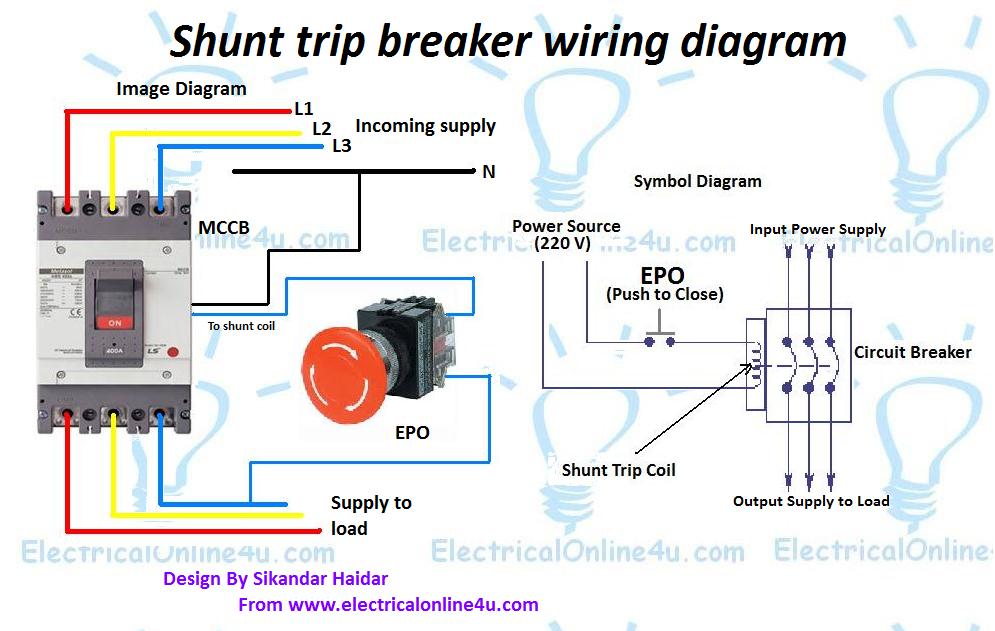
In the above MCCB shunt trip breaker wiring diagram. The incoming 3-phase 4-wire system supply is shown. The shunt breaker is 3 pole. Which is used for the 3-phase system. But the coil of the shunt is 220 VAC. So neutral is required also. The neutral wire is connected to the shunt coil. And line wire is controlled with a kill switch. The kill switch normally open contacts are used. Also, the symbol diagram is shown.
Also, read. Contactor Wiring diagram For 3-phase motor Earthing system and how earthing is protect us
- ← Automatic Water Level Controller Wiring Diagram
- Forward Reverse Starter With Timer 3 Phase Motor Wiring Diagram →
You May Also Like
What are Auxiliary Contacts and it’s working in Contactor?

Magnetic Contactor Animation Diagram
How to control a single phase motor from two points
8 thoughts on “ shunt trip breaker wiring diagram ”.
Plz Software name,where you design that circuit.
Hey what a brilliant post I have come across and believe me I have been searching out for this similar kind of post for past a week and hardly came across this. Thank you very much and will look for more postings from you. https://krmlight.com/shunted-vs-non-shunted/
I'll review this blog as An and it demonstrates how much exertion has been put into this. southend electrician
Nice reading zone
You need to experience a tournament for just one of the highest quality blogs over the internet. I’m going to suggest this site! https://royalcbd.com/product/cbd-gummies-10mg/
very nice post you have written, looking forward to see more https://bestlightfor.com/led-light/how-do-led-light-change-color/
Very helpful thank you
Watch and Download world's famous drama series Kurulus Osman in English on link below 👇 Kurulus Osman in English
📢Get free .com domain name and start your own website Free .com domain name
Crypto trading online course Join on link below Crypto quantum leap
📒 Read Home doctor book online Then you will be a doctor for your family Home Doctor Book
💰Create own NFTs and earn 1000$ Complete guide Create NFT
Join online YouTube course And be a professional YouTuber Tube Mastery and Monetization by matt
🦷Steel Bite Pro Best product for Teeth pain, cavities,teeth whitening and other oral health issues with money back guarantee Steel Bite Pro
Leave a Reply Cancel reply
Your email address will not be published. Required fields are marked *
Save my name, email, and website in this browser for the next time I comment.

IMAGES
VIDEO
COMMENTS
Illustration: Wiring Diagram for QO/QOB/QOU Shunt Trip. Skip To Main Content. USA Our Brands Item count in cart is 0 My Cart Item count in cart is 0 My Documents Login/Register User name ... I'd like to receive news and commercial info from Schneider Electric and its affiliates via electronic communication means such as email, and I agree to ...
Square D Shunt Trip Breaker Wiring Diagram. A Square D shunt trip breaker is a type of circuit breaker that can be remotely tripped or shut off in the event of an emergency. The shunt trip functionality allows for the breaker to be tripped from a remote location using a separate control voltage. This can be particularly useful in situations ...
Welcome to our tutorial on wiring a Shunt Trip on QO™ Circuit Breakers. In this step-by-step guide, we'll walk you through the process of wiring a Shunt Trip...
For example, if you have a Square D branded circuit breaker, you need a Square D shunt trip breaker wiring diagram. Before beginning installation, ensure that everything you need is within your reach. Also, always think of safety first! Step-By-Step Guide to Wire a Shunt Trip Breaker Wiring Diagram.
Product Line: Circuit Breakers. QO. Environment: Electrical Distribution Equipment. Resolution: Connect the appropriate voltage (ie. 120V to 240V for the -1021 suffix) to the two terminals on the shunt trip. Land the switch leg from the source contact on one terminal (either) and the neutral wire (L2 , X2 ) to the other terminal.
Connect the neutral wire to the neutral terminal, and the line wire to the line terminal. Make sure to tighten the screws securely to ensure proper electrical connection. Next, connect the shunt trip coil wires to the appropriate terminals on the circuit breaker. These wires are usually labeled as "Coil.".
Overall, wiring a shunt trip breaker is quite simple and direct. Step 1: Get familiar with your shunt trip breaker's wiring schematic. It's crucial for a safe and correct installation. Step 2: Find the two screws on the shunt trip unit - these are where you'll connect your control circuit wires. Step 3: Attach the control circuit wires ...
Once your workspace is ready, follow the step-by-step process. Start by turning off the main power supply. After that, connect the shunt trip breaker to the circuit. Be sure to connect the wires correctly: the black wire to the breaker terminal, the white neutral wire to the neutral bus bar, and the green or bare ground wire to the ground bus bar.
Wiring Diagrams for MasterPact NW Circuit Breakers. NOTE: All diagrams show circuit breaker open, connected and charged. A. Do not remove factory-installed jumpers between Z3, Z4 and Z5 unless ZSI is connected. B. Do not remove factory-installed jumper between T1 and T2 unless neutral CT is connected. Do not install jumper between T3 and T4. C.
Square D shunt trip circuit breaker wiring diagram is essential for anyone who wants to understand the intricate workings of this type of electrical device. This diagram provides a visual representation of how the shunt trip mechanism works, making it easier to understand and troubleshoot if any issues arise. In this article, we will delve ... <a title="Square D Shunt Trip Circuit Breaker ...
The PowerPact™ H-frame circuit breakers are designed to protect electrical systems from damage caused by overloads and short circuits. H-frame circuit breakers are available with either thermal-magnetic or Micrologic™ electronic trip units. The amperage ratings of the thermal trip elements are calibrated at 104°F (40°C) free air ambient ...
Masterpact MTZ Circuit Breaker Electrical Diagrams. Masterpact MTZ1 Fixed and Drawout Devices; ... Shunt Trip (MX), and Undervoltage Release (MN) with Basic Coils; Coil Characteristics ... , Masterpact, Micrologic, Phaseo, PowerPact, PowerView and Square D are trademarks and the property of Schneider Electric SE, its subsidiaries and affiliated ...
CASService explains how to wire a shunt trip breaker or contactor to an exhaust hood control package. For questions, please contact CASService at 1-866-784-6...
This video shows Shunt Trip Breaker Wiring Diagram. A shunt trip device is an optional accessory in a circuit breaker (MCCB) that mechanically trips the brea...
2. Catalog numbers and voltages for the Shunt Trip with Lockout. Operation. Apply control voltage to terminals. terminal strip on the right side of the breaker to trip. the circuit breaker. The Shunt Trip will. circuit breaker to trip when. greater than 75% o f the rated de voltage or 55% of the.
Here are some images of shunt coils and after that, we will discuss the shunt trip breaker wiring diagram with an image + symbol diagram. Now let's how to wire the shunt trip device (accessory), it's too simple as I have shown in the above shunt trip device images that a shunt coil has only two wires, just like a magnetic contactor or ...
Installation Instructions for Shunt Trip for R-Frame Series C Circuit Breakers and Molded Case Switches EATON CORPORATION www.eaton.com TABLE 1-1.SHUNT TRIP ELECTRICAL RATINGS DATA Averagecircuit breaker contact totalopening time approximately 62milliseconds,atrated voltage Endurance-500electrical operations.
Please look at the above shunt trip breaker wiring diagram. A mentioning fact is that here the tripping coil in the MCCB is rated for 230V single-phase supply. Let's discuss the connection procedure: At first we have to connect the neutral wire of the power supply to anyone terminal of the shunt trip coil. If its terminals are identified ...
The shunt trip (Fig. 1-1) provides remote controlled elec-trical tripping for the circuit breaker. It consists of an inter-mittent rated solenoid with a tripping plunger and a cutoff switch attached to a plug-in module. The plug-in module is mounted in slots in the top of the trip unit and occupies the accessory cavity in the circuit breaker frame.
Resolution: Use terminals 6 & 7 on the breaker to wire the shunt trip. Because it is AC, it is polarity insensitive. The other terminals are not operative. For more information please see instruction bulletin 48840-097-02. Released for: Schneider Electric USA.
In the above MCCB shunt trip breaker wiring diagram. The incoming 3-phase 4-wire system supply is shown. The shunt breaker is 3 pole. Which is used for the 3-phase system. But the coil of the shunt is 220 VAC. So neutral is required also. The neutral wire is connected to the shunt coil. And line wire is controlled with a kill switch.
shunt trip, and overcurrent trip switch warning (1)only qualified electrical personnel should be permitted to work on the equipment. (2)always de-energize primary and secondary circuits if a circuit breaker cannot be removed to a safe work location. (3)drawout circuit breakers should be levered (racked) out to the disconnect position.
Step 3: Connect the Shunt Trip Wires. After removing the existing circuit breaker, it is time to connect the shunt trip wires to the GE shunt trip breaker. The shunt trip wires are typically color-coded and must be connected to the appropriate terminals on the breaker. It is important to follow the manufacturer's instructions for proper wiring.