Accessibility Links
- Skip to content
- Skip to search IOPscience
- Skip to Journals list
- Accessibility help
- Accessibility Help
Click here to close this panel.
Purpose-led Publishing is a coalition of three not-for-profit publishers in the field of physical sciences: AIP Publishing, the American Physical Society and IOP Publishing.
Together, as publishers that will always put purpose above profit, we have defined a set of industry standards that underpin high-quality, ethical scholarly communications.
We are proudly declaring that science is our only shareholder.

Recent theory of traveling-wave tubes: a tutorial-review
Patrick Wong 1 , Peng Zhang 1 and John Luginsland 2
Published 3 June 2020 • © 2020 IOP Publishing Ltd Plasma Research Express , Volume 2 , Number 2 Citation Patrick Wong et al 2020 Plasma Res. Express 2 023001 DOI 10.1088/2516-1067/ab9730
Article metrics
4098 Total downloads
Permissions
Get permission to re-use this article
Share this article
Author e-mails.
Author affiliations
1 Department of Electrical and Computer Engineering, Michigan State University, East Lansing, MI 48824, United States of America
2 Confluent Sciences, LLC, Albuquerque, NM 87111, United States of America
Patrick Wong https://orcid.org/0000-0002-8437-6990
Peng Zhang https://orcid.org/0000-0003-0606-6855
John Luginsland https://orcid.org/0000-0002-6130-6156
- Received 3 March 2020
- Revised 8 April 2020
- Accepted 27 May 2020
- Published 3 June 2020
Peer review information
Method : Single-anonymous Revisions: 1 Screened for originality? Yes
Buy this article in print
The traveling-wave tube (TWT), also known as the traveling-wave amplifier (TWA) or traveling-wave tube amplifier (TWTA), is a widely used amplifier in satellite communications and radar. An electromagnetic signal is inputted on one end of the device and is amplified over a distance until it is extracted downstream at the output. The physics behind this spatial amplification of an electromagnetic wave is predicated on the interaction of a linear DC electron beam with the surrounding circuit structure. Pierce, known as the 'father of communications satellites,' was the first to formulate the theory for this beam-circuit interaction, the basis of which has since been used to model other vacuum electronic devices such as free-electron lasers, gyrotrons, and Smith-Purcell radiators, just to name a few. In this paper, the traditional Pierce theory will first be briefly reviewed ; the classic Pierce theory will then be extended in several directions: harmonic generation and the effect of high beam current on both the beam mode and circuit mode as well as 'discrete effects', giving a brief tutorial of recent theories of TWTs.
Export citation and abstract BibTeX RIS
This article was updated on 22 April 2021 to add permission lines to the figures.
Introduction
Throughout the history of commercial and defense applications involving electromagnetics, there has always been a high demand for microwave and millimeter wave amplifiers that offer both high power output and wide bandwidth. One candidate that may fulfill these stringent requirements is the traveling-wave tube (TWT), also known as the traveling-wave amplifier (TWA) or traveling-wave tube amplifier (TWTA). This device is widely used in satellite communications and radar applications.
It turns out that a viable method of amplifying a given electromagnetic wave is by passing this signal through a periodic structure and co-propagating it with a linear DC electron beam. To reduce complexities, this beam-circuit interaction takes place in vacuum. In such a set-up, the traveling wave gains energy at the expense of the kinetic energy of the electron beam. This continuous interaction and subsequent amplification of the electromagnetic wave happens over a distance (the length of the interaction region of the TWT) until the amplified wave is extracted at the output.
Before the invention of the TWT, the klystron amplifier (1935) was one of the first microwave amplifiers used [ 1 – 4 ]. This device though had several limitations. The most notable one is that the klystron had narrow bandwidth, as amplification is restricted to the resonant frequencies of the klystron cavities. The idea then came about to couple the individual cavities of a multi-cavity klystron to a common transmission line so that there may be a continuous in-phase interaction between beam and circuit [ 3 , 4 ]. This eventually led to the development of the traveling-wave tube amplifier. Figure 1 shows the evolution of the klystron to the traveling-wave tube.
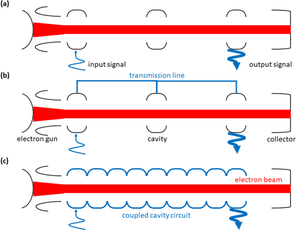
Figure 1. Schematic diagram showing the evolution of a multi-cavity klystron (a) to a traveling-wave tube amplifier (c). (b) shows the multi-cavity klystron with its cavities coupled to a common transmission line.
Download figure:
Rudolph Kompfner of England, interestingly an architect by profession, was the first to propose the idea of a traveling-wave tube. He and Nils Lindenblad of the United States used a metallic helix as the circuit structure for propagating the signal in phase with the centered pencil electron beam in vacuum and are credited with being the first to create the TWT as it is known today [ 5 , 6 ]. Prior to this, Haeff proposed a similar idea but had the electron beam on the outside of the circuit, leading to poorer efficiency [ 7 ]. Kompfner's invention of the TWT then aroused the intense interest of John R Pierce who then laid the foundation of the TWT theory and was later known as the 'father of communications satellites' [ 8 ]. A schematic diagram of a modern TWT is shown in figure 2 .
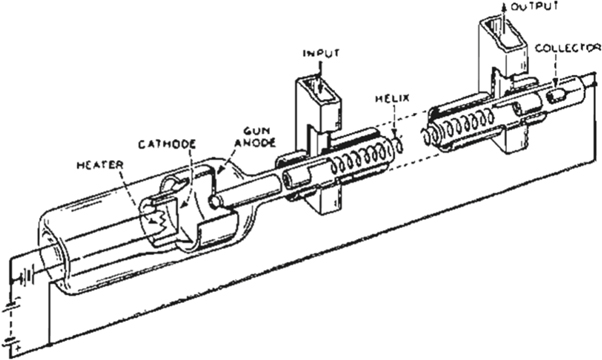
Figure 2. Schematic diagram of a traveling-wave tube amplifier. There are many components to a TWTA. In this paper, we will concentrate only on the middle section, the helix, of the above figure: the beam-circuit interaction region. The slow-wave circuit shown here is a helix (with support rods). Image from [ 9 ]. This diagram of helix TWT has been obtained by the author(s) from the Wikipedia website, where it is stated to have been released into the public domain. It is included within this article on that basis.
As can be seen in figure 2 , an actual TWT is a complex device, consisting of components (left: cathode, electron gun, etc) that create and form the electron beam, the beam-circuit interaction region (middle: helix, electron beam, etc), and components (right: collector) that collect the 'spent' beam. Each of these topics in and of themselves constitute a library of study. In this paper, the focus will be restricted to the physics in the beam-circuit interaction region within the helix (figure 2 ). In particular, the standard beam-circuit mode coupling theory of Pierce will be examined. Using the Pierce theory as a basis, we will then extend it to describe effects originally neglected by Pierce: harmonic generation and the effects of high beam current on the circuit as well as connecting the continuous wave picture of Pierce to a discrete circuit formulation.
To begin, it must be emphasized that the operation of a TWT, or virtually any beam-driven microwave source, is predicated on the interaction of an electron beam in vacuum with an in-phase, co-propagating electromagnetic wave on a circuit structure. As such, it is instructive to analyze each of these two components: beam and circuit separately and then describe their interaction, as was also done by Pierce [ 10 ]. This method of analysis and mode coupling is not restricted to TWTs, rather, the techniques presented here are quite general and applicable to all beam-circuit interactions between charged particles and electromagnetic radiation.
The electron beam
As can be seen in figure 2 , the electron beam is formed outside of the beam-circuit interaction region. Electrons are boiled off from a thermionic cathode (thermionic emission) or emitted from a material using strong electric fields (field emission). In either scenario, a voltage is externally applied to the cathode and this is essentially the kinetic energy of the beam entering the interaction region. We will denote the kinetic energy of this beam by voltage V b , corresponding to a DC beam velocity v 0 . Invoking conservation of energy in the non-relativistic regime,
For simplicity, it is assumed that there are no temperature effects on the beam so that the beam is 'cold' or mono-energetic (introducing temperature effects will be slightly more complicated but will essentially introduce a spread in electron velocities centered around a mean value). We further assume that the DC beam motion is one-dimensional, i.e., we implicitly assume that there is an infinite axial magnetic field confining the beam. In reality, this is provided by an external solenoid or periodic permanent magnets.
The two externally adjustable parameters of the beam: the DC beam voltage V b and the DC beam current I 0 control the unperturbed electron beam velocity v 0 and the electron charge density ρ 0 , respectively. In the absence of any perturbation, the electron beam travels through vacuum in the axial direction with these unperturbed properties.
The electromagnetic circuit
There are of course other SWS designs for different purposes. A listing and description of some of these SWS designs can be found in [ 11 ]. Traditionally speaking, all of the structures are metallic, but much effort has, in recent years, been placed in studying metamaterial SWS's [ 12 , 13 ]. These have very different dispersion characteristics than their metallic counterparts leading to different gain properties. However, their beam-circuit interaction may still be captured by the mode-coupling theory of Pierce (in the small-signal regime); the physics and mathematics of the beam and circuit coupling remains the same. Different beam configurations (e.g. pencil beam versus sheet beam versus annular beam) will also play a role in the gain characteristics of the tube (see [11a] for a comparison between pencil and annular beams and [11b] for a discussion comparing sheet beams, an 'unwrap' of annular beams, to pencil beams; [ 14 ] talks about the plasma frequency reduction factor for different beam configurations, a topic we will come back to soon). Still to this date though, the helix SWS coupled with a pencil electron beam remains the 'go-to' for high power microwave amplification because of its wide bandwidth and ease of construction.
The reason why a helix TWT may offer a wide bandwidth is qualitatively illustrated in figure 3 .
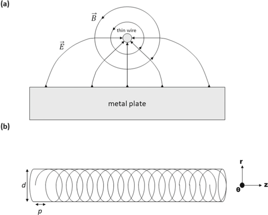
Figure 3. (a) Depiction of the TEM fields of a thin wire over a perfectly conducting metal plate. (b) The formation of a helix TWT from 'wrapping' the set-up in (a).
where E C is the circuit electric field, Γ 0 is the effective propagation constant of this circuit wave (= β ph with an imaginary part to account for attenuation in the circuit), and K is known as the interaction impedance (essentially a pure geometrical quantity that is a proportionality constant between the voltage and current of the 'cold' no beam system). Assuming time and spatial harmonic fields, equation ( 3 ) may be written as:
β 0 (or just β in the literature) is called the fundamental, and β n ( n ≠ 0) is called the n th space harmonic.
What we have allured to but have neglected to discuss thus far is the space-charge electric field E SC coming from the beam, with good reason. Space-charge calculations in general are notoriously difficult, and there is no general model that can capture this internal self-force of the beam. It turns out, see the section 'Beyond Pierce', that one model of space-charge effects is intimately tied to the higher-order passbands of the circuit and the higher-order beam modes. This higher-order interaction was not initially captured by Pierce as his analysis was concerned with the interaction of the fundamental passband and beam mode only. It should be noted though that he did hypothesize the role of higher-order passbands of the circuit on space charge; for now, we will group space-charge effects under the term 'QC' or 'Q', following Pierce's original notation. Thus, accessing space-charge effects in TWTs boils down to finding an expression for 'Q', known as Pierce's AC space-charge parameter.
The Beam-Circuit Interaction and Pierce's theory of mode-coupling
Now that we have described the beam and circuit separately, how do they interact in such a way to produce amplification of the injected signal? When the beam enters the beam-circuit interaction region and feels the circuit wave, the electrons in the beam will respond to the sinusoidal nature of the electric field of the signal. Consequently, one can imagine that some electrons will be accelerated by the accelerating portion of the wave and some electrons will be decelerated by the decelerating portion of the wave. This leads to the formation of electron bunches in the electron beam. These bunches in turn cause the electric field in the circuit to increase by inducing more current in the circuit; electron motion inducing currents in external circuits can be attributed to the famous Shockley-Ramo Theorem [ 20 ]. The resulting amplitude increase in the electric field in the circuit causes more bunching in the beam. The physical mechanism is succinctly illustrated in Gilmour's book [ 1 , 2 ].
From a wave mechanics picture, a pair of space-charge waves on the electron beam are created from the beam interacting with the circuit wave. These space-charge waves on the beam are analogous to longitudinal pressure waves in air consisting of compressions and rarefactions. In this case, we have the fast and slow space-charge waves that co-propagate on the electron beam with the circuit wave. The energy difference from the slowing-down of the electrons in the beam to the slow space-charge wave phase velocity is given to the circuit, causing amplification of the circuit wave. This beam-circuit interaction has proven to be effective: the growth of the input signal, at least in the small-signal regime, is exponential with distance along the tube [ 1 , 2 ]. TWT power gain of 60 dB (1 million times) can be realized [ 21 ].
As stated before, the classical theory of beam-structure interactions in a TWT was developed by Pierce [ 10 ], whose treatment also provided the foundations for the understanding and design of a wide range of contemporary sources such as free-electron lasers [ 4 , 22 – 24 ], Smith-Purcell radiators [ 4 , 23 – 26 ], gyrotron amplifiers [ 4 , 26 – 30 ], metamaterials TWTs [ 12 , 13 , 31 ], and NonLinear Transmission Line (NLTL) based sources [ 32 ]. We will present the standard Pierce theory and further develop it to indicate other novel effects not previously considered by Pierce. Pierce described the energy transfer mechanism in terms of the interaction between the space-charge waves on the electron beam and the electromagnetic mode supported by the electromagnetic circuit. Amplification of a signal of frequency ω is described by the complex wavenumber β that is a solution of what is known as the Pierce dispersion relation, which, in its most basic form [ 1 , 3 , 4 , 10 , 13 , 22 – 24 , 26 – 30 ], is a third-degree polynomial for β(ω) . This dispersion relation describes the coupling between the beam mode and the circuit mode [ 33 , 34 ]. It has been used in the validation of non-linear, large-signal numerical codes in the small-signal regime.
An interesting side note is that unlike most topics, such as plasma physics and electromagnetic wave theory, here we consider the propagation constant as a function of the frequency. That is, one is generally given a frequency (the frequency of the input signal to be amplified) and is tasked with finding the corresponding propagation constant, which is in general complex. The imaginary part corresponds to either the growth (amplification) or decay (attenuation) of the wave in the system.
We are now in a position to self-consistently solve the governing equations for the beam (equations ( 1 ), ( 2 )) and circuit (equation ( 3 )) to yield solutions describing the evolution of both, as a coupled system. With some manipulation, the three equations can be combined to yield:
To simplify matters (this was back in the day when solving quartic polynomials was a chore!), a common approximation is to assume that C is small and to neglect the backward circuit wave, as it is primarily the forward waves that contribute to the gain of a TWT downstream. Doing so and using the notation of Pierce, the so-called 3-wave dispersion relation reads:
For comparison purposes (c.f. equation ( 5 ') below), Pierce's 3-wave dispersion relation for β reads:
It should be noted that reflection from the ends and waves near the band edges cannot be accounted for by Pierce's 3-wave theory. A classical look into Pierce's 4-wave theory and its reduction to the 3-wave theory is provided by Birdsall and Brewer [ 35 ]. The importance of the 4-wave description, and the effects of reflection on the TWT stability may be found in [ 36 – 38 ].
Beyond pierce
The above was a tour-de-force through electron beam dynamics and electromagnetic wave theory culminating in a simple yet powerful description of beam-circuit mode coupling and interaction in a TWT. One must remember that this type of analysis was done back in the early to mid-20th century. Many advancements in terms of modeling and mathematics and the advent of scientific supercomputing have taken analyses of such devices to new heights. Consequently, more complex and accurate descriptions on the inner workings of a TWT exist. Nevertheless, there is still a subtle charm to a simple theory. Not only can it give a 'back-of-the-envelope' assessment of a given problem but it can provide great physical insights into the nature of such interactions and processes. In this vein, we will now attempt to relax some of the assumptions of Pierce and extend his theory in a simple manner and draw further insights into the beam-circuit interaction. The topics covered here will be harmonic generation and space charge in TWTs as well as 'discrete cavity' effects, relating TWT analysis to klystron analysis. A brief synopsis of the first two topics are provided in the following paragraphs.
The classical Pierce theory was formulated for a single (fundamental) frequency, that of the input signal. However, in a TWT with an octave bandwidth or greater, in particular the widely used helix TWT, the second harmonic of the input signal may also be within the amplification band and thus may also be generated and amplified, with no input at this second harmonic frequency. An extension to the Pierce formulation that incorporates the generation of harmonics will be presented here. It is shown that the second harmonic arises mostly from a newly discovered dynamic synchronous interaction instead of by the kinematic orbital crowding mechanism that is the most dominant harmonic generation mechanism in other microwave devices. The methodology provided here, which is a natural extension of Pierce's original theory, may be applicable not only to TWTs but to other high-power microwave sources.
In beam-circuit interactions, the space-charge effect of the beam is important at high beam currents. In Pierce's TWT theory, as stated before, this space-charge effect is modelled by the parameter which he called Q in the beam mode. A reliable determination of Q remains elusive for a realistic TWT. Previously, Wong et al [ 39 ] constructed the first exact small-signal theory for the beam-circuit interaction for the tape helix TWT, from which Q may be unambiguously determined. In the process of doing so, it was discovered that the circuit mode in Pierce's theory must also be modified at high beam current, an aspect overlooked in Pierce's original analysis. This circuit mode modification is quantified by an entirely new parameter called q , introduced for the first time in TWT theory. For the example using a realistic tape helix TWT, we find that the effect of q is equivalent to a modification of the circuit phase velocity by as much as two percent, which is a very significant effect. A brief summary of q will be provided here.
Harmonic generation in TWTs
The subject of harmonic generation in a TWT has traditionally been studied in the non-linear, large-signal regime. We will not delve into large-signal theory here as it is beyond the scope of this text. The theory itself is more complete as it can not only capture non-linear phenomena such as saturation, wave-trapping of beam electrons, etc. but can also recover the linear, small-signal regime. However, it is much more complicated than the relatively simple linear theory presented here thus far and simple insights, which we stress here, cannot be easily drawn. We will note here that large-signal TWT theory and also the study of harmonics of the input signal can be traced back to the classical paper by Nordsieck [ 40 ], who also provided the first analysis of TWT efficiency. References may be made to Tien et al , Rowe, Giarola, and Dionne [ 41 ] whose subsequent works relied heavily on Nordsieck's initial theory.
Taking a step back, it is well-known in klystrons that the dominant cause of harmonics of the input signal to be generated is due to linearized orbital motion from an input signal leading to orbital crowding, which leads to harmonic generation kinematically [ 3 , 42 ] (see figure 5 below). In such scenarios, the extreme case of charge overtaking may also occur and contribute to harmonic generation. It was not until recently that such a theory on harmonic content in the beam current of a TWT was developed by Dong et al [ 43 ] in the small-signal regime. In that work, the linearized electron orbits might lead to a second harmonic AC current as high as 25% of the DC beam current, and this was favorably compared to the large-signal TWT code CHRISTINE [ 44 ].
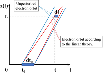
Figure 5. An (exaggerated) illustration of harmonic generation due to orbital crowding. Crowding in the linear orbits may lead to harmonic current generation, as shown in klystron theory [ 3 ] and TWT theory [ 43 ].
A little after Dong et al 's paper, another source of harmonic content in a TWT was discovered: weak non-linearities in the electron orbits. It turns out, with respect to the RF power output, that this source of harmonic generation is much more important as it possesses the property of synchronism between the beam and circuit in both space and time , the underpinning concept behind the operation of TWTs. The effect of orbital crowding described in the preceding paragraph is negligible in comparison [ 45 ].
The main idea behind this alternative view on harmonic generation in TWTs stems from carrying out higher-order expansions of the governing equations for the beam [recall: Pierce's small-signal analysis is a linear theory; this is the answer to the above question posed in Footnote 1]. These minor corrections on the quantities of the beam corrects the linear quantities of Pierce [ 46 ] but also turn out to be the harmonics; basically, we regard the quantities of interest: the electric field (potential), beam density and velocity (current) to be represented by a Fourier series. This interpretation then is a quasi-linear theory.
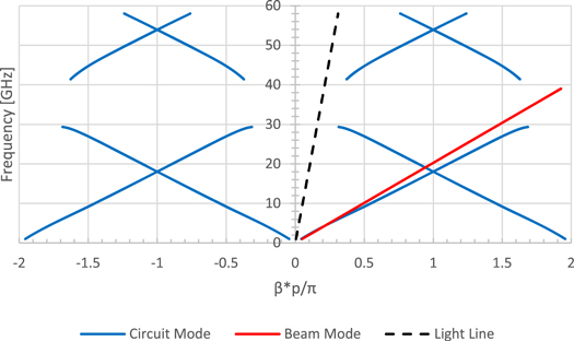
The electromagnetic signal causes the electrons in the beam to bunch. To first order, these bunches are at the frequency of the signal itself, leading to Pierce's linear theory. The orbits of the beam electrons though are better represented at higher orders and thus contain more frequencies of the input signal. In response, the circuit picks up each of these frequencies individually (Maxwell's Equations are linear). The circuit then not only supports an amplifying signal at the fundamental (input) frequency but also a spectrum of harmonics of the original signal, all being spatially amplified. This of course can only happen if the spectrum of frequencies is within the bandwidth of the TWT: any frequency outside of the characteristic bandwidth will not be supported by the structure. The ubiquitous helix structure is one such circuit structure that can have octave bandwidth, as evidenced by figure 4 above.
Space-charge effects in TWTS
Let us now go back to the notorious problem of space-charge effects, or finding a closed form expression for Q in the Pierce picture. Many theories have been proposed that attempt to give a general formulation for calculating Q for a general beam and circuit structure. A treatise of the subtlety of this problem is given by Lau and Chernin [ 49 ], who ultimately advance the idea that Q is due to the interaction of the beam with the higher-order circuit modes (passbands higher than the fundamental). This interpretation of Q originating from residual interactions between beam and circuit, the 'remainder,' was actually also proposed by Pierce [ 10 ], who quickly abandoned such an interpretation [ 49 ], adhering instead to what the standard Pierce theory is now: the interaction between the fundamental circuit and beam modes.
Physically speaking, the calculation of the space-charge parameter boils down to calculating the 'reduced' plasma frequency ω q of the beam. Like a plasma, the beam, which can be considered to be a non-neutral plasma, has a natural frequency called the electron beam plasma frequency, which is the frequency of the space-charge waves in an unbounded medium. However, in reality, the beam is bounded in the sense that it has a definite shape and is enclosed by the finite circuit structure. Thus, the plasma frequency of the beam is 'reduced'. In this view, the task is to calculate the reduction factor to the plasma frequency that accounts for the circuit structure (including the SWS, taking into account, for example, the 'field leakage' in the opened sections of a helix). It turns out that this calculation is intimately tied to the higher-order circuit modes mentioned in the preceding paragraph. Before we delve deeper into the mystery of space charge, it is instructive to first understand the prior art.
A study using the pedagogical model of a dielectric TWT that consists of a planar dielectric slab and sheet electron beam was done by Simon et al [ 51 ]. In that model, where an exact 'hot tube (including the beam)' dispersion relation may be readily derived, the idea of the higher-order circuit modes yielding Q was established conclusively. In addition, that paper showed how to accurately evaluate the Pierce parameters once a closed analytic form was found. This model however is deficient in that there is no periodic slow-wave structure in this dielectric TWT (the dielectric slows down the wave), so higher harmonics in the beam mode are excluded.
If, however, we may find an exact dispersion relation for the circuit structure including all of the geometric complexities and the beam dynamics for a realistic TWT, then possibly we stand a chance at determining an expression for Q . As in [ 49 ] and [ 51 ], we may cast the derived analytic dispersion relation into the form of Pierce (equations ( 5 ) or ( 6 )) and extract an exact expression for the Pierce parameters. In [ 15 ], a formally exact treatment of the tape helix TWT without the electron beam (the 'cold-tube' dispersion relation) was presented by Chernin et al Later, in [ 52 ], this analysis was expanded on by the inclusion of the electron beam, giving a formally exact 'hot-tube' dispersion relation. However, because of the complexity of the analytical dispersion relation, it was unfeasible to rewrite it in a Pierce-like form. The alternative then was to numerically solve the dispersion relation and 'backtrack' to find what the Pierce parameters ought to be. In the process of doing so, it was found that it was necessary to introduce a new parameter, termed q , in order for the equations to be satisfied [ 39 ].
This new parameter q turns out to modify the circuit mode in much the same way that the original space-charge parameter Q that we were looking for modifies the beam mode, shown here for the 3-wave dispersion relation:
Because of this, the interpretation of q has been attributed to the effects of space charge of the beam on the circuit mode, i.e. beam loading of the circuit. This view is supported by the fact that q increases with beam current [ 39 ]. From a dispersion diagram perspective, much like how Q arises from the interaction of the fundamental beam mode with the 'remainder' of the circuit modes apart from the fundamental circuit mode, q arises from the interaction of the circuit mode with the beam modes of order higher than the fundamental, completing the symmetry. Because the dielectric TWT discussed above does NOT contain any periodic components that make up the slow-wave structure, the new parameter q = 0 in this model as there are no spatial harmonics of the beam [ 39 ].
To demonstrate the effects of this q term, a plot of the roots of equation ( 6 a ) using the standard definition of C and ubiquitous models of Q (Branch and Mihran and sheath helix [ 14 , 44 ]) are given in figure 6 below along with the roots of the exact hot-tube dispersion relation for a tape helix. The three roots represent the resultant three waves from the beam-circuit interaction in the system: a neutral root, a decaying (complex with negative imaginary part) root, and an amplifying (complex with positive imaginary part) root. We, of course, care about the amplifying part as it represents the linear gain of the TWT. The other two waves however are also important as they constitute what is known as the launching loss of the TWT (where the remainder of the initial power of the signal is channeled to). Note that adding the fourth root (from solving the original 4-wave equation ( 5 )) representing the backward propagating wave will change the results. Qualitatively, the three (main) roots will remain the same, and the fourth root will be a neutral root with a negative propagation constant.
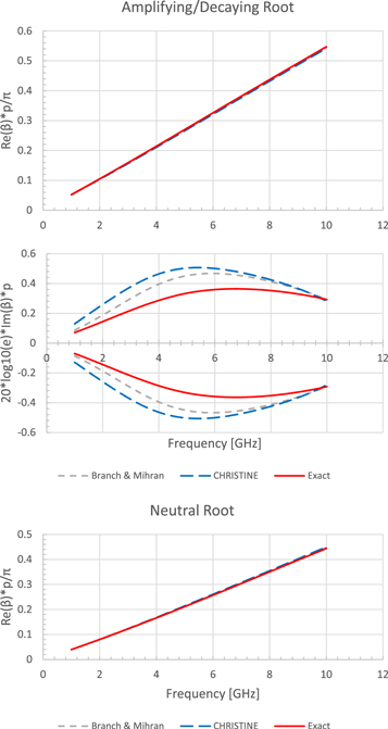
Figure 6. Plot of the three roots (propagation constant β ) as determined from: Pierce theory with Q modeled by Branch and Mihran (gray, dashed) [ 14 ], Pierce theory with Q modeled by the sheath helix model as used by CHRISTENE [ 44 ] (blue, dashed), and the exact dispersion relation (red, solid) as a function of input signal frequency. Image adapted from [ 39 ]. © [2018] IEEE. Reprinted, with permission, from [ 39 ].
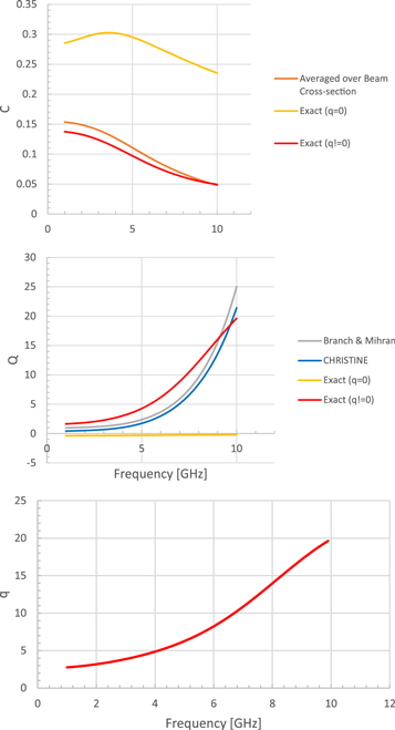
As can be seen in figure 6 , there are differences in the solution and hence the predicted gain of a helix TWT depending on the models used. From the numerical solution to the exact hot-tube dispersion relation (red in figure 6 ), one can find what the Pierce parameters, namely C and Q here, ought to be. These are plotted as a function of frequency below in figure 7 along with the parameters' respective models/usual definitions. The new necessary parameter q is also plotted. We see that if q = 0, the values of the traditional Pierce parameters take on unrealistic values, necessitating this new parameter to fit the prediction of the exact dispersion relation to Pierce theory.
Discrete cavity analysis of TWTs
While the formulation thus far presented has centered around the groundwork laid by Pierce and therefore has concentrated on treating the beam-circuit interaction as a continuum, it is also important to consider 'discrete cavity' effects, relating back to the klystron-TWT picture presented in figure 1 . After all, the beam-circuit interaction is not always purely continuous in a real system and having discrete effects allows for more freedom on the part of the microwave engineer to account for various effects, as will be briefly discussed below, not amenable to standard Pierce theory. This also allows us to tie the TWT to other microwave structures such as the klystron [ 54 ] and the magnetron [ 28 ], where there is not a continuous interaction.
As we have shown, Pierce theory reduces the complex geometry of the slow wave circuit to individual traveling waves that must then interact with a driving beam. In high frequency tubes [ 55 ], as well as potential designs with relatively small numbers of cavities, the detailed adjustment of an individual cavity, either due to manufacturing errors, or for attempts to control oscillation and reflections, might be necessary. This can be challenging for Pierce theory, where we have implicitly used a wave analysis. One way to handle this is to simply allow the phase velocity mismatch, the gain parameter, and the cold-circuit loss to vary spatially in equations ( 6 )–( 9 ) [ 48 ]. Alternatively, another potential avenue of theoretical development comes from treating the individual cavities as discrete circuit elements with explicit coupling between the cavities. This allows individual cavities to be tuned, both in frequency and in shunt impedance, to engineer the dispersion between the beam and the electromagnetic structure, giving additional degrees of freedom to the tube designer. In terms of Pierce theory, however, the individual cavities and their coupling results in a set of normal modes. These normal modes have well-defined phase and group velocities due to the explicit nature of the coupling, just as in standard Pierce theory, but allow for non-uniform cavities to be used. Naturally, the transition from discrete normal modes to a wave formulation is well understood, as the number of cavities tends to large (infinite) values.
It should be noted that the discrete theory of TWTs has a long history. As a consequence, many developments have been made to account for various effects and ultimately advance the theory. Some more recent examples of this are listed in [ 56 ]. There is current, on-going theoretical, simulation, and experimental work in better understanding the transition from a discrete number of cavities to an infinite continuum in a tube, from the effects that a finite number of cavities introduces to the continuous wave interaction picture of Pierce. New tube designs with a low number of cavities have been set up for this purpose of determining the limits of the Pierce theory and the transition point to the discrete cavity regime. Here, we will lay out the basics of the theoretical formulation.
For illustration purposes, we can start by considering a traveling wave structure with just four cavities. After this pedagogical introduction, we will apply the method to a real TWT. We assume a cavity can be modeled as a circuit with bulk parameters that can be well described as a harmonic oscillator. This circuit then develops a voltage due to electron beam current, source signals, and coupling between the cavities. If we define the harmonic oscillator operator L as
we can then write the following set of equations for our four cavity system:
where ( A , B , C , D ) represent the cavity voltages, Z represents the cavity impedance, S is a general input source, c is the coupling between the cavities, and I ( x ) represents the electron beam current at a given cavities' location. This current naturally has the impact of the previous cavities, so needs to represent a history of the current interaction with the upstream cavities. Here, we only study the cold tube properties, so we set these currents to zero, and set the source term to zero. Furthermore, take the usual actions of normalizing the resonant frequency of the isolated cavities to one without loss of generality, assuming sinusoidal solutions, and setting the quality factor to infinity, equation ( 11 ) can then be recast into matrix form,
This equation has a number of nice features—first, it is tri-diagonal, which allows considerable linear algebra tools to be used. Second, all of the cavity details can be included in the matrix M . Thus, equation ( 12 ) gives us the homogenous solution to our slow wave structure. Sources can be added to the right hand side of equation ( 12 ) as we go forward.
Here, however, we will continue to focus on the eigenvalues of this system. These eigenvalues give the resonant frequencies of the system and the eigenvectors are the characteristic modes. Analytically, we can exploit the fact that tri-diagonal systems have a recursion relationship for the determinant. Furthermore, we use the fact that we have only four cavities and thus have a quartic equation, which is actual bi-quadratic. Alternatively, we can use Octave's symbolic package to solve for the roots of the system, or numerically solve for them. Because the resulting equations are polynomial in nature, the numerical solution with Octave is quite tedious, even for four cavities. Once a given root is found, the equations need to be deflated by hand for Octave's numerical solver to find the next root [ 57 ]. Despite this challenge, analytic, symbolic and numerical all gave the same resonant frequencies for our four cavity system:
where we note, for clarity, that ' c ' is the coupling between adjacent cavities.
We can then use equation ( 13 ) to solve for the eigenvectors of the system. The plot of these is shown in figure 8 . Initially, these eigenvectors were difficult to interpret, but noting that these are normal modes, the shape of these fields makes more sense. To do this, we need to fix the boundary conditions outside of the cavity structure—a typical choice is to set the fields to zero, which would be consistent with a TWT slow wave structure inside a cutoff waveguide. With these conditions, the normal modes become the typical phase advance per cavity if one assumes an additional 'virtual cavity' with amplitude of zero on either side of the slow wave structure. This is shown in figure 9 . Comparing figures 8 and 9 , we see that the orange points in the plot, representing the cavity field amplitude, are following a given sinusoidal pattern, albeit with a difference in phase for two of the eigenvectors between the Octave result and our normal model analysis. These modes can be directly tied to the phase advance per cavity, which is given by m π/4, where m is an integer. With this insight, it is possible to plot the dispersion relationship for our model with frequency versus phase advance (or mode number) as shown in figure 10 .
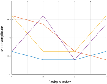
Figure 8. Eigenvectors for the four cavity system roots given in equation ( 13 ) from Octave. This plots mode amplitude versus cavity number. Thus, the horizontal axis gives the axial location of the field.
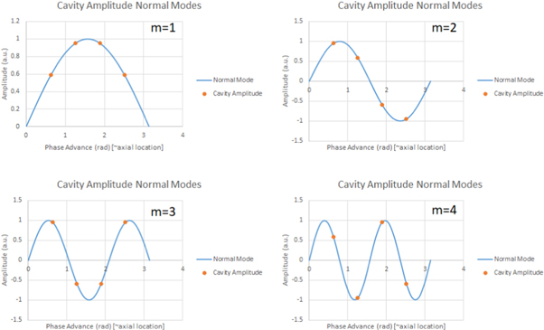
Figure 9. Analytic normal mode analysis of the 4 cavity eigenvectors.
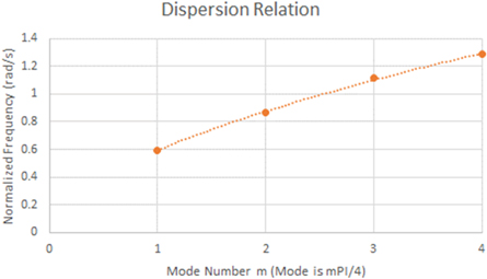
Figure 10. Dispersion relation for our four cavity circuit model. Cavity coupling c = 0.4.
It is worth noting that figure 10 has the typical characteristics of dispersion relationships that we expect from relatively short slow wave structures. The correct phase advance and mode shape have been found. Additionally, variation in the number of cavities and/or the cavity coupling allows the relative 'flatness' of the curve near the π mode to be observed, consistent with experimental and frequency domain analysis of TWT structures. Finally, it is a positive sign that we have tested the computational tools that are necessary to handle realistic numbers of cavities for a non-trivial if small, example, and verified these tools against analytic results.
Next, we extend the coupled-cavity circuit model to simulate a realistic TWT [e.g. using the parameters from [ 55 ]], as opposed to the four-cavity proof-of-principle. The effort proceeds by building a tridiagonal matrix with the harmonic oscillator operator on the diagonal and the coupling term on the bands. For our exercise here, we assume no ohmic loss and symmetric coupling between the cavities. In this case, we have a Toeplitz matrix, and there are recursion relations for the eigenvalues. This allows us to compute the dispersion relationship from the normal modes. Because the harmonic oscillator operation has two roots, there are two harmonic oscillator modes for the dispersion relation. The dispersion relation is shown in figure 11 . This result is in excellent agreement with HFSS results published in the literature [ 55 ].
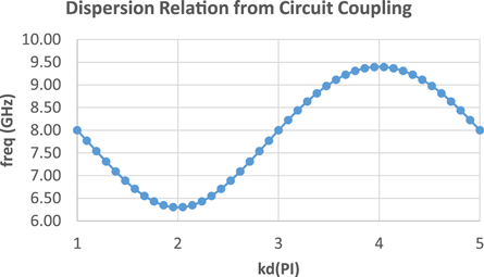
Figure 11. Dispersion relation for a 20 cavity sine waveguide TWT constructed from a coupled cavity approach. Individual cavities have a resonant frequency of 8 GHz and the dimensionless coupling between the cavities is c = 0.19.
The next passband is found in a similar manner, with the resonant frequency of an individual cavity changed to 12.5 GHz and the coupling reduced to c = 0.03. The physical reason for the reduction in the cavity coupling for the second passband is the higher frequency allows the electromagnetic waves to be concentrated more tightly to the structure. It is also worth noting that both passbands have significantly more coupling than the klystron cases previously examined. This is simply the nature of the traveling wave tube structure. The second passband is shown in figure 12 .
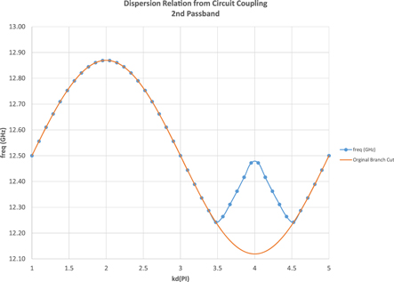
Figure 12. Second passband for the sine waveguide TWT with individual cavity frequency of 12.5 GHz and cavity coupling of c = 0.03.
Comparing the coupled circuit model and HFSS does unveil an interesting feature. Simply taking one harmonic oscillator mode (or 'branch cut' as it is referred to in figure 12 ) of the normal mode structure yields the orange curve in figure 12 . This is clearly different than that seen in the HFSS calculation. However, switching to the other harmonic oscillator mode allows us to find the correct dispersion relationship for both modes in the second passband. The jump between harmonic oscillator modes is not clear, and further work needs to be done to understand why this additional step is necessary to reproduce the second passband. That said, we believe this kink is physical, and structures like these are often found in band edges of TWTs. Additionally, the HFSS calculations were run on a unit cell, and it is not clear if that makes it easier to choose between the harmonic oscillator modes [ 58 ].
We have demonstrated that a coupled circuit model can reproduce the electromagnetic structure of a full TWT, and that this allows one to add spatial non-uniformity to the slow wave circuit. Additional work that we have done shows that as the number of cavities becomes large, the normal mode analysis naturally transitions to a wave description. This provides an explicit link between standard Pierce theory (wave) and a means to incorporate finite length effects, internal reflections, manufacturing errors, and individual cavity differences into a Pierce style analysis.
Concluding remarks
In conclusion, we have just glossed over the mode-coupling theory of Pierce in describing the beam-circuit interaction of a TWT. We have talked qualitatively and quantitatively about the linear DC electron beam and the electromagnetic signal on the surrounding structure constituting the circuit, separately, and then how both interact to produce the desired amplification of the signal. Even though Pierce's classical theory is a linear (so-called 'small-signal') theory, it is still powerful and widely used. The key to its endurance is its simplicity as well as tradition, as it was the first comprehensive theory to describe the inner workings of a TWT. Its simplicity allows for relatively fast 'back-of-the-envelope' calculations and insights into the underlying mechanisms of beam-circuit interaction. Here, we stress what we believe are the core ideas of Pierce's theory: synchronous interaction between and coupling of the beam and circuit producing amplification of the input signal.
In keeping with this, we attempt to provide several natural extensions to the Pierce theory to describe phenomena not previously considered in the small-signal regime. These include harmonic generation (from dynamical synchronous interaction between the beam and circuit in an octave bandwidth tube) and beam-loading on the circuit (stressing the symmetry between beam and circuit and their coupling). Additionally, we have discussed the links between normal mode analysis associated with coupling individual cavities and its relationship to Pierce theory.
It should be stressed that this paper is by no means a comprehensive overview of TWTs. This paper is much too immature to tackle such a subject. We wish to introduce the reader to the world of TWTs and beam-circuit interactions via the classical theory of Pierce and try to extend the core ideas behind the theory to tackle more modern topics: harmonic generation, space-charge effects, and discrete cavity effects. There are still many topics to explore. The reader is encouraged to look through the references (which is by no means extensive), especially [ 59 ] on the history of the TWT in telecommunication. Louisell's textbook [ 60 ] provides excellent, more in-depth discussions on many of the topics addressed here, especially space-charge waves (c.f. Chapters 2 and 3).
Acknowledgments
This work was supported by the Air Force Office of Scientific Research (AFOSR) Multidisciplinary University Research Initiative (MURI) Grant No. FA9550-18-1-0062, Air Force Office of Scientific Research (AFOSR) YIP Grant No. FA9550-18-1-0061, and the Office of Naval Research (ONR) YIP Grant No. N00014-20-1-2681.
Certain images in this publication have been obtained by the author(s) from the Wikipedia website, where they are stated to be in the public domain. Please see individual figure captions in this publication for details. To the extent that the law allows, IOP Publishing disclaim any liability that any person may suffer as a result of accessing, using or forwarding the image(s). Any reuse rights should be checked and permission should be sought if necessary from Wikipedia and/or the copyright owner (as appropriate) before using or forwarding the image(s).
The authors would also like to thank Professor Y. Y. Lau for valuable discussions and his advice and encouragement.
What happens if we keep more terms in the expansion? See the section, 'Beyond Pierce' below.
Travelling Wave Tube (TWT)
A travelling wave tube is a high power amplifier used for the amplification of microwave signals up to a wide range. It is a special type of vacuum tube that offers an operating frequency ranging between 300 MHz to 50 GHz .
Travelling wave tubes are non-resonant structures that offer continuous interaction of applied RF field with the electron beam over the entire length of the tube. Due to this reason, it provides wider operating bandwidth.
Content: Travelling Wave Tube
Basic concept.
- Construction
Need of Slow-Wave Structure
- Applications
Travelling wave tubes are abbreviated as TWT . It is majorly used in the amplification of RF signals. Basically a travelling wave tube is nothing but an elongated vacuum tube that allows the movement of electron beam inside it by the action of applied RF input.
The movement of an electron inside the tube permits the amplification of applied RF input. As it offers amplification to a wide range of frequency thus is considered more advantageous for microwave applications than other tubes.
It offers average power gain of around 60 dB . The output power lies in the range of few watts to several megawatts.
A travelling wave tube is basically of two types one is helix type and the other is coupled cavity. Here in this section, we will discuss the detailed construction and working of a helical travelling wave tube.
Construction of Travelling Wave Tube
The figure here shows the constructional structure of a TWT:
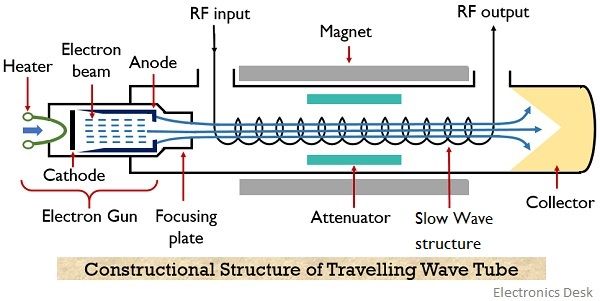
As we can see that the helical travelling wave tube consists of an electron gun and a slow-wave structure . The electron gun produces a narrow beam of the electron. A focusing plate is used that focuses the electron beam inside the tube.
A positive potential is provided to the coil (helix) with respect to the cathode terminal. While the collector is more positive than the coil (helix). In order to restrict beam spreading inside the tube. A dc magnetic field is applied between the travelling path by the help of magnets.
The signal which is needed to be amplified is provided at one of the ends of the helix, present adjacent to the electron gun. While the amplified signal is achieved at the opposite end of the helix.
In the figure, we can clearly see that attenuator is present along both the sides of the travelling wave tube. This is so because travelling wave amplifiers are high gain devices, so in case of poor load matching conditions, oscillations get build up inside the tube due to reflection.
Thus in order to restrict the generation of oscillations inside the tube attenuators are used.
Attenuators are basically formed by providing a metallic coating over the surface of the glass tube. Aquadag or Kanthal are majorly used for this.
It is to be noteworthy that a slow-wave structure is considered here, the reason is to maintain continuous interaction between the travelling wave and electron beam.
We know that the velocity of the electromagnetic wave is very much higher when compared with the phase velocity of the electron beam emitted by the electron gun.
Basically the RF wave applied at the input of TWT propagates with the speed of light (i.e., 3 * 10 8 m/s ). While the propagating velocity of the electron beam inside the tube is comparatively smaller than the velocity of RF wave.
If we try to somehow accelerate the velocity of the electron beam, then it can be accelerated only to a fraction of velocity of light. So it is better to reduce the velocity of the applied RF input in order to match the velocity of the electron beam.
Therefore, a slow-wave structure is used that causes a reduction in the phase velocity of the RF wave inside the TWT.
The slow-wave structures can be of different types like a single helix, double helix, zigzag line, corrugated, coupled-cavity or ring bar type etc.
A single helix slow-wave structure is formed by wounding a wire of element like tungsten and molybdenum in the form of a coil. The helical shape of the structure slows the velocity of the wave travelling along its axis to a fraction of about one-tenth of c.
This is so because due to the helical shape of the structure, the wave travels a much larger distance than the distance travelled by the beam inside the tube. So, in this way, the speed of wave propagation depends on the number of turns or diameter of the turns.
More specifically we can say that change in pitch can vary the speed of wave propagation inside the tube.
The equation given below shows the relation of phase velocity of the wave with the pitch of the helix:

: c = velocity of light (3 * 10 8 m/s)
V P = phase velocity in m/s
P = pitch of helix in m
d = diameter of the helix in m
Therefore, this causes continuous interaction between the RF input wave and the electron beam as the velocity of propagation of the two is not highly different. As such interaction is the basis of working of TWT thus slow-wave structures are used.
Working of Travelling Wave Tube
Till now we have discussed the complete constructional structure of TWT. Let us now understand how the signal gets amplified while travelling inside the tube.
The applied RF signal produces an electric field inside the tube. Due to the applied positive half, the moving electron beam experiences accelerative force. However, the negative half of the input applies a de-accelerative force on the moving electrons.
This is said to be velocity modulation because the electrons of the beam are experiencing different velocity inside the tube.
However, the slowly travelling wave inside the tube exhibits continuous interaction with the electron beam.
Due to the continuous interaction, the electrons moving with high velocity transfer their energy to the wave inside the tube and thus slow down. So with the rise in the amplitude of the wave, the velocity of electrons reduces and this causes bunching of electrons inside the tube.
The growing amplitude of the wave resultantly causes more bunching of electrons while reaching the end from the beginning. Thereby causing further amplification of the RF wave inside the tube.
More specifically we can say that forward progression of the field along the axis of the tube gives rise to amplification of the RF wave. Thus at the end of the tube an amplified signal is achieved.
The positive potential provided at the other end causes collection of electron bunch at the collector.
The magnetic field inside the tube restricts the spreading of the beam as the electrons possess repulsive nature.
However, as the TWT is a bidirectional device . Therefore, the reflected signal causes oscillations inside the tube. But as we have already discussed earlier that the presence of attenuators reduces the generation of oscillations due to reflected backwave.
Sometimes despite using attenuators, internal impedance terminals are used that puts less lossy effects on the forward signal.
Applications of TWT
- Travelling wave tubes are highly used in continuous wave radar systems.
- These amplifying tubes also find application in broadband receivers for RF amplification.
- TWT’s are also used to get high power output in satellite transponders.
So from the above discussion, we can conclude that no resonant structure is present in the interaction space. Thus provides amplification up to a wide bandwidth operating range.
However, the input and output coupling arrangements must be considered carefully as they limit the operating range.
Related Terms:
- Transmission Lines
- IMPATT Diode
- Backward Wave Oscillator
Leave a Comment Cancel Reply
Your email address will not be published. Required fields are marked *

Traveling Wave Tube Working(TWT):
Like the multicavity klystron, the Traveling Wave Tube Working is a linear-beam tube used as a microwave amplifier. Unlike the klystron, however, it is a device in which the interaction between the beam and the RF field is continuous. The TWT was invented independently by Kompfner in Britain and then Pierce in the United States, shortly after World War II, Each of them was dissatisfied with the very brief interaction in the multicavity klystron, and each invented a slow-wave structure in which extended interaction took place. Because of its construction and operating principles, as will be seen, the TWT is capable of enormous bandwidths. Its main application is as a medium- or high-power amplifier, either CW or pulsed.
TWT Fundamentals:
In order to prolong the interaction between an electron beam and an RF field, it is necessary to ensure that both are moving in the same direction with approximately the same velocity. This relation is quite different from the multicavity klystron, in which the electron beam travels but the RF field is stationary. The problem that must be solved is that an RF field travels with the velocity of light, while the electron beam’s velocity is unlikely to exceed 10 percent of that, even with a very high anode voltage. The solution is to retard the RF field with a slow-wave structure. Several such structures are in use, the helix and a waveguide coupled-cavity arrangement being the most common.
Description:
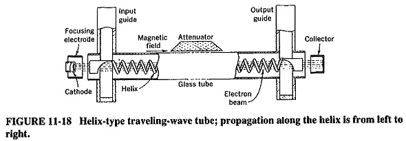
A typical Traveling Wave Tube Working using a helix is shown in Figure 11-18. An electron gun is employed to produce a very narrow electron beam, which is then sent through the center of a long axial helix. The helix is made positive with respect to the cathode, and the collector even more so. Thus the beam is attracted to the collector and acquires a high velocity. It is kept from spreading, as in the multicavity klystron, by a dc axial magnetic field, whose presence is indicated in Figure 11-18 though the magnet itself is not shown. The beam must be narrow and correctly focused, so that it will pass through the center of the helix without touching the helix itself.
Signal is applied to the input end of the helix, via a waveguide as indicated, or through a coaxial line. This field propagates around the helix with a speed that is hardly different from the velocity of light in free space. However, the speed with which the electric field advances axially is equal to the velocity of light multiplied by the ratio of helix pitch to helix circumference. This can be made (relatively) quite slow and approximately equal to the electron beam velocity. The axial RF field and the beam can now interact continuously, with the beam bunching and giving energy to the field. Almost complete bunching is the result, and so is high gain.
The Traveling Wave Tube Working may be considered as the limiting case of the multicavity klystron, one that has a very large number of closely spaced gaps, with a phase change that progresses at approximately the velocity of the electron beam. This also means that there is a lot of similarity here to the magnetron, in which much the same process takes place, but around a closed circular path rather than in a straight line.
Bunching takes place in the Traveling Wave Tube Working through a process that is a cross between those of the multicavity klystron and the magnetron.
Electrons leaving the cathode at random quickly encounter the weak axial RF field at the input end of the helix, which – is due to the input signal. As with the passage of electrons across a gap, velocity modulation takes place and with it, between adjacent tums, some bunching. Once again it takes theoretically no power to provide velocity modulation, since there are equal numbers of accelerated and retarded electrons. By the time this initial bunch arrives at the next turn of the helix, the signal there is of such phase as to retard the bunch slightly and also to help the bunching process a little more. Thus, the next bunch to arrive at this point will encounter a somewhat higher RF electric field than would have existed if the first bunch had not made its mark.
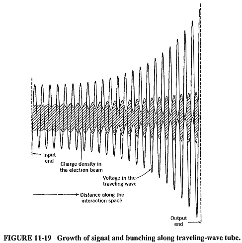
The process continues as the wave and electron beam both travel toward the output end of the helix. Bunching becomes more and more pronounced until it is almost complete at the output end. Simultaneously the RF wave on the helix grows (exponentially, as it happens) and also reaches its maximum at the output end. This situation is shown in Figure 1149.
The interaction between the beam and the RF field is very similar to that of the magnetron. In both devices electrons are made to give some of their energy to the RF field, through being slowed down by the field, and in both devices a phase-focusing mechanism operates. It will be recalled that this tends to ensure that electrons bunch and that the bunches tend to keep arriving in the most favored position for giving up energy. There is at least one significant difference between the devices, and it deals with the methods of keeping the velocity of the beam much the same as that of the RF field, even though electrons in the beam are continually retarded. In the magnetron this is done by the dc magnetic field, but since there is no such field here (no component of it at right angles to the direction of motion of the electrons, at any rate), the axial dc electric field must provide the energy. A method of doing this is to give the electron beam an initial velocity that is slightly greater than that of the axial RF field. The extra initial velocity of electrons in the beam balances the retardation due to energy being given to the RF field.
Practical Considerations:
Among the points to be considered now are the various types of slow-wave structures in use, prevention of oscillations, and focusing methods.
Slow Wave Structures:
Although the helix is a common type of slow-wave structure in use with TWTs, it does have limitations as well as good points. The best of the latter is that it is inherently a nonresonant structure, so that enormous bandwidths can be obtained from tubes using it. On the other hand, the helix turns are in close proximity, and so oscillations caused by feedback may occur at high frequencies. The helix may also be prevented from working at the highest frequencies because its diameter must be reduced with frequency to allow a high RF field at its center. In turn, this presents focusing difficulties, especially under operating conditions where vibration is possible. Care must be taken to prevent high power from being intercepted by the (by now very small-diameter) helix; otherwise the helix tends to melt.
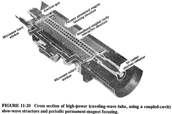
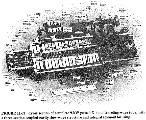
A suitable structure for high-power and/or high-frequency operation is the coupled-cavity circuit, used by the Traveling Wave Tube Working of Figure 11-20. It consists of a large number of coupled (actually, overcoupled) cavities and is reminiscent of a klystron with a very large number of intermediate cavities. It acts as a distributed filter, with a principle of operation that is identical to that of pulse forming networks. Essentially, there is a continuous phase shift progressing along the adjoining cavities. Because these are overcoupled, it may be shown that the system behaves as a bandpass filter. This gives it a good bandwidth in practice but not as good as the exceptional bandwidth provided by helix TWTs. This type of slow-wave structure tends to be limited to frequencies below 100 GHz, above which ring-bar and other structures may be employed.
Prevention of oscillations:
Figure 11-19 shows the exponential signal growth along the traveling-wave tube, but it is not to scale the actual gain could easily exceed 80 dB. Oscillations are thus possible in such a high-gain device, especially if poor load matching causes significant reflections along the slow-wave structure. The problem is aggravated by the very close coupling of the slow-wave circuits. Thus all practical tubes use some form of attenuator (which has the subsidiary effect of somewhat reducing gain). Both forward and reverse waves are attenuated, but the forward wave is able to continue and to grow past the attenuator, because bunching is unaffected. With helix tubes, the attenuator may be a lossy metallic coating (such as aquadag or Kanthal) on the surface of the glass tube. As shown in Figure 11-20, with a coupled-cavity slow-wave structure there are really several (three, in this case) loosely coupled, self-contained structures, between which attenuation takes place. It should be noted that Figure 11-19 shows a simplified picture of signal and bunching growth, corresponding to a TWT without an attenuator.
Related Posts:
Losses in transmission lines, noise in information, network protocols in digital communication, fiber optics history, planar triode construction, ratio detector circuit, basic radar system block diagram, color tv transmission and reception, vertical deflection circuit in tv.
Thank you for visiting nature.com. You are using a browser version with limited support for CSS. To obtain the best experience, we recommend you use a more up to date browser (or turn off compatibility mode in Internet Explorer). In the meantime, to ensure continued support, we are displaying the site without styles and JavaScript.
- View all journals
- My Account Login
- Explore content
- About the journal
- Publish with us
- Sign up for alerts
- Open access
- Published: 19 November 2020
Multiple-beam and double-mode staggered double vane travelling wave tube with ultra-wide band
- Zheng Zhang 1 ,
- Cunjun Ruan 1 , 2 ,
- Ayesha Kosar Fahad 1 ,
- Chenyu Zhang 1 ,
- Yiyang Su 1 ,
- Pengpeng Wang 1 &
- Wenlong He 3
Scientific Reports volume 10 , Article number: 20159 ( 2020 ) Cite this article
1610 Accesses
10 Citations
Metrics details
- Electrical and electronic engineering
- Electronics, photonics and device physics
This paper presents design, fabrication and cold test of an ultra-wide band travelling wave tube (TWT) with planar alignment multiple pencil beams. The fundamental double-mode of staggered double vane slow wave structure (SDV-SWS) rather than the only one mode are put forward and adopted to match with the same electron beam to increase the bandwidth greatly. Simultaneous planar alignment multiple pencil beam tunnels are designed to improve interaction impedance and then to enhance output power, gain, efficiency, growth rate. The transmission performance of a two-stage 51-period SDV-TWT in G-band with structure attenuator between two sections shows that it indeed has an ultra-wideband performance from 81 to 110 GHz. By using computer numerical control machining, the SDV-SWS was manufactured and a detailed cold test was conducted. Good agreement is found at the wide band, where S 21 is above − 5 dB and S 11 is below − 10 dB. 3D PIC simulations with double-mode multiple-beam SDV-TWT within total length of 70 mm show that it can get a nearly 2120 W peak output power, a 42.5 dB corresponding gain and a 10.7% electron efficiency at 94 GHz with a 22.1 kV beam voltage and a 3 × 0.15A beam current. The 3 dB bandwidth of our double-mode SDV-TWT can achieve about 29 GHz.
Double-mode and double-beam staggered double-vane traveling-wave tube with high-power and broadband at terahertz band
A piecewise sine waveguide for terahertz traveling wave tube
Relativistic Surface Wave Oscillator in Y-Band with Large Oversized Structures Modulated by Dual Reflectors
Introduction.
Recently, millimeter and terahertz technology has received great interest due to their potential applications in diverse modern scientific fields including advanced telecommunication systems, high-resolution radars, biomedical imaging and sensing 1 , 2 , 3 . Much of attention has been paid to vacuum electronic devices (VEDs) and vacuum integrated amplifier technologies, especially for their capability of producing high power and high efficiency with thermal robustness and reliability in a compact package 4 , 5 . Travelling wave tubes (TWTs) have been demonstrated to be one of the most significant amplification devices of all the VEDs which can provide high output power in a broadband 6 , 7 . Slow-wave structures (SWSs), as a key part of TWTs influence the performance considerably, so the investigation of SWSs has always been an important section to meet the design requirements of TWTs in millimeter and terahertz band. Up to now, many new types of planar SWSs such as folded waveguide (FWG) 8 , sine waveguide 9 and staggered double vane (SDV) 10 have been presented to solve the issues caused by increased working frequency. The size of SWSs becomes smaller which makes the traditional fabrication technique hard to meet matching tolerance requirement, and the traditional helix-TWTs and coupled-cavity TWTs cannot get a high output power and a wide band at millimeter and terahertz band. Thus, these new types of planar SWSs really have advantages that they can be easily fabricated by using 2D plane manufacturing technology with the development of microelectron mechanical systems, e.g. computer numerical control (CNC) and UV-LIGA.
Comparison with the widely used planar FWG, the SDV-SWS have been proved to achieve high power, high efficiency, high growth rate, high interaction impedance, and wideband compatibly with sheet beam at W-band and G-band 11 , 12 , 13 , 14 . A design study using SDV-SWSs combined with a sheet beam has shown that an output power of over 1 kW should be possible from 90 to 95 GHz 15 . However, the formation and transportation of such a micro-miniature intense sheet electron beam can be really difficult particularly in beam channel with sub-millimeter structures, and long transmission distance with high current density. To avoid these problems, planar alignment multiple pencil beam SDV-SWSs have been designed with a 2250 W output power and a 15 GHz bandwidth 11 . Not only can pencil beam TWTs give the good solution to above issue, but they have additional advantages of simple RF input/output coupler design compared to sheet beam SDV-TWT, for the RF signal which is naturally cut-off in pencil beam tunnel. Recently, the significant progress for the fabrication and measurement of sheet bam SDV-TWT is performed in UC-Davis in 2017 4 , the experimental results show that the 3 dB bandwidth of 14 GHz with output pulse power of 11 W, and 3 dB bandwidth of 6 GHz with output pulse power of 107 W have been achieved with the fabricated SDV-TWT in G-band. However, the improvement of bandwidth for SDV-TWT amplifier is still under potentials with quite a long and difficult way to go in this field.
In this paper, to further improve the bandwidth, keep the high output power and avoid the serious problems of sheet beam formation and long distance transportation, instead of using the only fundamental single mode to match with the electron beam, the fundamental double-mode SDV-SWS with planar alignment three-pencil beam in W-band is studied thoroughly. It is found that the beam-wave matching band indeed increases as twice compared to our previous work 11 . Also, the interaction impedance is also about two times higher than that of sheet beam SWS in the same band. Then, a simple coupler is used to get a good transmission performance, and a two-stage SWS structure is also designed to suppress the reflection and oscillation for the SDV-TWT. Moreover, the two stage SDV-SWS for W-band TWT is fabricated by the CNC machining system, and a cold test is conducted by using a vector network analyzer, good agreements are achieved compared with the simulation results. Finally, 3D PIC simulation shows that it can obtain a high output power of nearly 2120 W at 94 GHz with a two-stage 51-period SWS-TWT, the gain of 42.5 dB and the efficiency 10.7%. The 3 dB bandwidth about 29 GHz from 81 to 110 GHz can be achieved, which is almost twice than that of our previous work (15 GHz) 11 . Thus, our double-mode, two-stage and planar alignment three-pencil beam SDV-TWT indeed has good performances of high power and broadband in millimeter and terahertz band.
High-frequency characteristics
A single period of staggered double vane slow-wave structure is given in Fig. 1 , which can form a strong symmetric axial electric field distribution along the direction of electron movement 16 . Also, compared to sheet beam, the planar alignment pencil beam tunnels can constrain the electric field better to increase the axial electric field 11 , 17 . So, sheet beam tunnels are replaced by three pencil beam tunnels as is shown in the figure, where l is the width of the vane, h is the height of the vane, p is the length of the single period SDV-SWS, g is the distance from the upper vane to the lower vane, tr is the radius of the pencil beam tunnel and d is the distance between the edges of two adjacent beam tunnels.
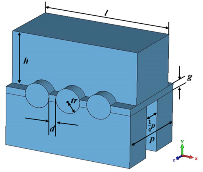
3-D schematic of a single period of SDV-SWS. It is a physical inverse model, where the blue part is a vacuum section and the background is the actual material like copper.
Dispersion characteristics
In SWS, the fundamental mode (TE 10 mode) is designed to interact with electron beam. Due to the symmetry of staggered double vane structure, solutions of the dispersion equation of electromagnetic field can be divided into two cases. One is the odd mode corresponding to mode 1 in Fig. 3 , the other is the even mode corresponding to mode 2. So mode 1 and 2 are both belong to the fundamental mode. The central frequency and the synchronous voltage for the SDV-TWT are set to f 0 = 94 GHz and V 0 = 22 kV respectively. We choose phase shift \({\varvec{\phi}}\) =2.7π to avoid the lower cutoff oscillation 18 and to match the 22 kV electron beam with Brillouin curves of mode 1 and mode 2 as much as possible, which means we hope our SDV-SWS operates at the first double-mode which are designed to promote the bandwidth. The detail analysis will be given in Fig. 3 . Thus, we can calculate the value of synchronous phase velocity and the length of the single period SDV-SWS p by using (1) and (2), where v p is the phase velocity of electrons, c is the speed of light in vacuum.
Then, the effects of each structure parameters on dispersion characteristics for SDV-SWS can be studied thoroughly, and the results are similar to our previous work 11 . As l increases, the whole phase velocity decreases; as h increases, the phase velocity of high frequency decreases but that of low frequency keeps the same. Then, when tr increases, we can regard it as the width of the vane l increases and the height of the vane h decreases, so the whole phase velocity decreases but the decrease in phase velocity of low frequency is more than that of the high frequency as is shown in Fig. 2 a. Next, as d increases, like the width of the vane l increases, the whole phase velocity decreases as is shown in Fig. 2 b. Structure parameter g has little effect on dispersion characteristics but has a great effect on interaction impedance and transmission characteristics.
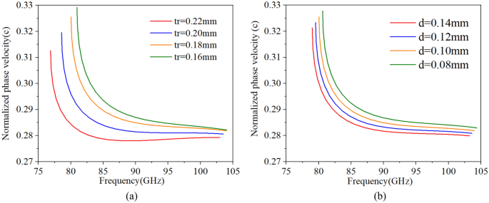
Effects of tr ( a ) and d ( b ) on dispersion characteristics.
Considering the influence of dispersion, interaction impedance, beam current and fabrication, we determined and optimized the structure parameters which are given in Table 1 . Then, the final optimized dispersion characteristics is shown in Fig. 3 . We can see that the SDV-SWS can be operated in the fundamental double modes, beam-wave velocity matching band is good enough to reach 29 GHz from 81 to 103 GHz (mode 1) , and 104 GHz to 110 GHz (mode 2). It is indicated that, we can use the same electron beam to interaction with these two modes, which may promote the bandwidth for the beam-wave interaction in the design of SDV-TWT. There is a small band gap between mode 1 and mode 2, the gap is from 103.4 to 103.9 GHz and it is possible to generate self-excited oscillation in this narrow band gap due to high impedance. However, the TWT device we designed has a ultra-wide band from 81 to 110 GHz. The gap between two modes are very small comparing to the ultra-wide band. Certainly, it is best to avoid using 103–104 GHz frequency band in the real engineering work in case of oscillations. Besides, we have conducted the hot test simulation to calculate the output signal of each frequency carefully, especially at the frequency of 103 GHz and 104 GHz. The background material is set to copper, and the results show that there is no any oscillation at this two frequency, the output signal is stable and the frequency spectrum is pure.
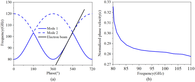
The dispersion characteristics of SDV-SWS, Brillouin curves ( a ) and normalized phase velocity ( b ), where mode 1 from 80 to 103 GHz and mode 2 from 104-120 GHz match the same electron beam line.

Interaction impedance
As the main characteristic for the design of TWT, the interaction impedance \({{\varvec{k}}}_{{\varvec{c}}{\varvec{n}}}\) can determine the gain, efficiency, and growth rate of the tube, which is given as follow.
where P w is the power along the z -axis for the direction of electron movement, E zn is the amplitude of the spatial harmonic component which is synchronous with the electron beam, and β n is the n th spatial harmonic’s phase constant. So, we can see that E zn is a key parameter that determines the interaction impedance directly. Based on our previous work, we find that the value of tr influences the E z at the center of the middle beam tunnel. Moreover, compared to sheet beam tunnels, the pencil beam tunnels have a much stronger E z . That can be explained as pencil beam tunnels can constrain the electric field better in a smaller space to form the stronger field, so the interaction impedance obtains a big increase 11 .
We set the radius of pencil electron beams as br = 0.12 mm, the average interaction impedance for 9 × 3 points on the multiple pencil beam cross-section and 5 × 15 points on the sheet beam cross-section 19 can be calculated with the same height of beam tunnel, which is shown in Fig. 4 . We can conclude that the interaction impedance of pencil beam SDV-SWS is over 2Ω in beam-wave matching band, which is indeed almost twice higher than that of sheet beam SWS which is over 1Ω as is shown in Fig. 5 .
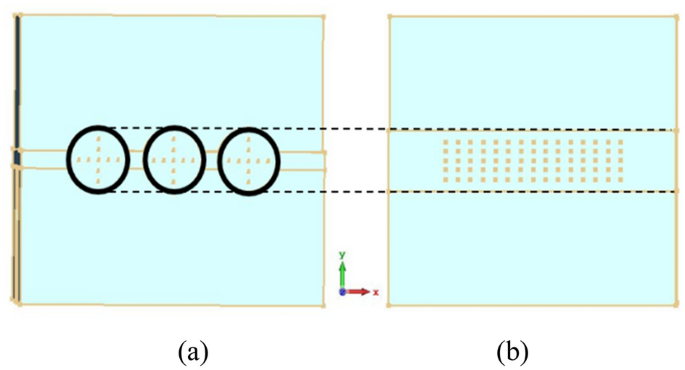
Cross sections of two kinds of beam tunnels, multiple pencil beam tunnels ( a ) and sheet beam tunnels ( b ). The diameter of pencil beam tunnels and the height of sheet beam tunnels are about the same.
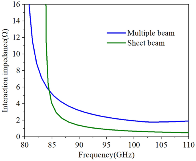
Interaction impedance of two kinds of SWS.
Transmission characteristics simulation, fabrication and cold test
Transmission characteristics simulation results.
Usually, the RF signal cannot be naturally cut off in the sheet beam tunnel which means an input/output coupler needs to be designed to decrease the reflection of SDV-TWT. However, for our three-pencil beams SDV-TWT, the RF signal is naturally cut off in pencil beam tunnels, so this time we do not need to use a complicated coupler as previous works 20 , instead, a simpler and easier coupler structure was used to be connected to standard rectangle waveguides as is shown in Fig. 6 . Besides, a two-stage structure is used as an available way to suppress the oscillation of reflection wave when the number of periods is increased greatly for SDV-SWS, and an attenuator that is used to connect two-stage structures and to suppress the oscillation and reflection is designed. Compared with the single-beam system, the plane multi-beam system could significantly increase the electron beam cross-sectional area and then effectively increase the output power and gain. Although the operating mode is cut off for the electron beam channel, there is still some space between the upper and lower vane which could generate other non-working modes competition like high-order-mode, so we still need an attenuator between Port 3 and 4 to suppress the oscillation and reflection. Considering the fabrication technique of this whole structure and the roughness of metal circuit walls, PEC cannot used as background material for the simulation. Instead, oxygen-free copper was set as background materials and the conductivity was set to 2.25 × 10 7 S/m in W-band 21 . Using CST’s time domain solver 27 , 28 , we get the transmission characteristics of our two-stage 51-periods SDV-SWS with first stage of 22 periods and second stage of 29 periods. The simulation results for S-parameters is given in Fig. 7 , which shows that the whole structure has a high return loss (S 11 < − 10 dB) and a low transmission loss in a broad band from 81 to 110 GHz. Just like we designed, this double-mode two-stage multiple pencil beam SDV-TWT has an ultra-wide band of about 29 GHz which is about twice than that of our previous structure 11 .
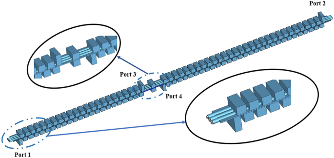
Schematic of two-stage TWT(22 + 29, 51 periods) with attenuator and coupler structure.
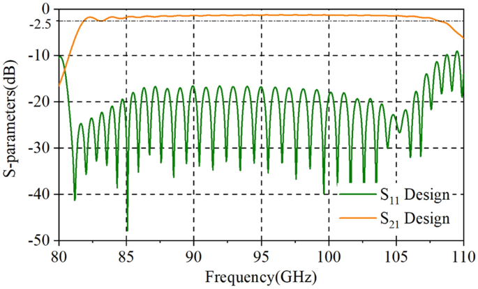
Transmission characteristics of the SDV-SWS together with input and output couplers.
Fabrication
To verify our design, we fabricated our SDV-TWT with its SWS by using a CNC precision vertical machining technique which directly mills of circuit structures into bulk Oxygen-free high conductivity (OFHC) copper with two halves. Compared to UV-LIGA, CNC technique increases design flexibility and simplicity. And, different from the structures made of silicon and coated with a thin metal layer, it provides better thermal robustness due to superior thermal and electrical properties. Moreover, compared to additive manufacturing developing recently, it can obtain lower surface roughness 22 , 23 , 24 , 25 . Although there are some drawbacks of CNC milling like only one structure can be fabricated at one time and the geometry design is limited 26 , we still chose this CNC milling technique to manufacture our W-band SDV-TWT. Because the number of our circuit structures is with multiple periods and same geometry design, and the rectangular structures can be precisely controlled by CNC.
Owing to our RF signal input ports which is designed to connect with standard WR-10 flanged waveguide ports directly, the manufacturing structure is simple, and the process of reflection measurements is easy to accomplish. Figure 8 a shows images of fabrication structure outside the SDV-TWT where the length, width, and thickness of the whole structure is 85.8 mm, 20 mm and 10 mm respectively. It was machined into two halves through the center of beam tunnels and eight pairs of small matching round holes were designed to further reduce the alignment errors that are drilled at both wide sides. Figure 8 b shows images of SDV-SWS and attenuator where the first shorter stage is 22 periods and the second longer stage is 29 periods, which is separated by a 0.9 mm-length and 0.77 mm-height Bragg attenuator. Figure 8 c is a partial enlargement of the top left corner of Fig. 8 b and shows planar alignment three pencil beam tunnels in detail.
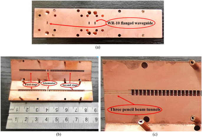
Photos of the fabrication structure outside ( a ), inside ( b ) and ( c ). ( a ) The port in the left is corresponding to Port 1 in Fig. 6 and the right one is Port 3. ( b ) Eight pairs of small matching round holes and eight short copper bars are adopted at the edge of the structure. ( c ) Local enlarging photo of three pencil beam tunnels.
Cold test and analyses
A vector network analyzer (VNA) (AV3672C, 10 MHz–43.5 GHz) which is connected to two frequency extenders (AV3645A) with a frequency range of 75–110 GHz was used for cold test. It utilized a backward wave oscillator (BWO) and can be used for quick testing of MEMS fabricated and CNC machined devices. Test setup for cold test of our SDV-TWT is shown in Fig. 9 . Based on our adjusted structure, two-port S-parameter measurements are conducted after careful calibration (AV32141).
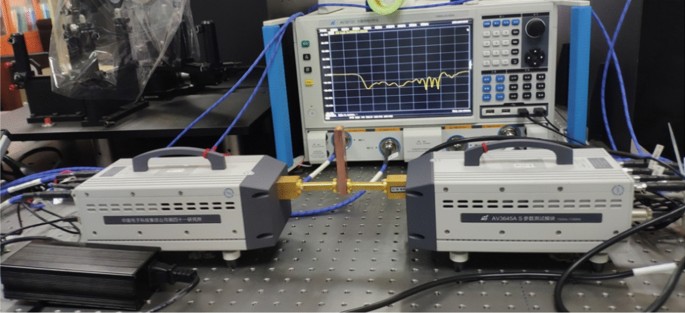
Photos of testing process with a room temperature.
We conducted several tests to reduce the impact of misalignment issues as much as possible and to get the best results in the process of testing. We tested the return loss (S 11 ) and the transmission loss (S 21 ) of each port in the two-stage our for fabrication SDV-SWS, and the results are about the same as shown in Fig. 10 . It shows S-parameters results, where S 11 is below -10 dB from 82 to 104 GHz, with a little bit increase from 104 to 110 GHz. And, S 21 in high frequency band (from 89 to 110 GHz) is above − 5 dB but in low frequency band (from 82 to 89 GHz) is below − 5 dB. Compared to our previous TWT structure, this double-mode two-stage indeed increases the 3 dB bandwidth though it is not as much as simulation results, where the return loss is lower and the transmission loss is higher than that of actual measurement. The main reason may be lies in the deviations of fabrication. We can remodel our TWT simulation structure and calculate the effects to verify our suppositions. The conductivity of actual fabricated parts may be different from that of simulation with the roughness and materials. We calculate several conductivities of materials (+ ∞, 5.95 × 10 7 , 2.25 × 10 7 , 1.00 × 10 7 ) as background. The results in Fig. 11 show that as the conductivity decreases, the return loss (S 11 ) increases a little but the transmission loss (S 21 ) increases a lot in high-frequency band, which means the low conductivity may cause the increases of transmission loss. For the reflection increases, it could be attributed to the surface quality/finish and roughness of the SWS ports which there may be some projections that increases the reflection. To verified this, we have changed the simulation model and calculated the S-parameter results as is shown in Fig. 12 . Clearly, the reflection increases in high frequency band. However, for the differences in low frequency band, we account that maybe due to this frequency band from 85-90 GHz is close to the cut-off frequency of the slow wave structure we designed, the transmission loss becomes bad and increases. Besides, there could be a little resonance in the SDV-SWS for much of periods structure at this 85-90 GHz band which causes transmission loss increases remarkably but the return loss almost remains the same. So, we conclude that it is the deviations of fabrication and the roughness of the OFHC copper that caused the differences for the simulation and test results and we really need to pay attention to this in the future processing process..
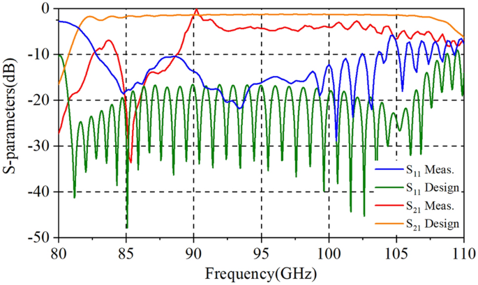
S-parameters results of measurement and design structures.
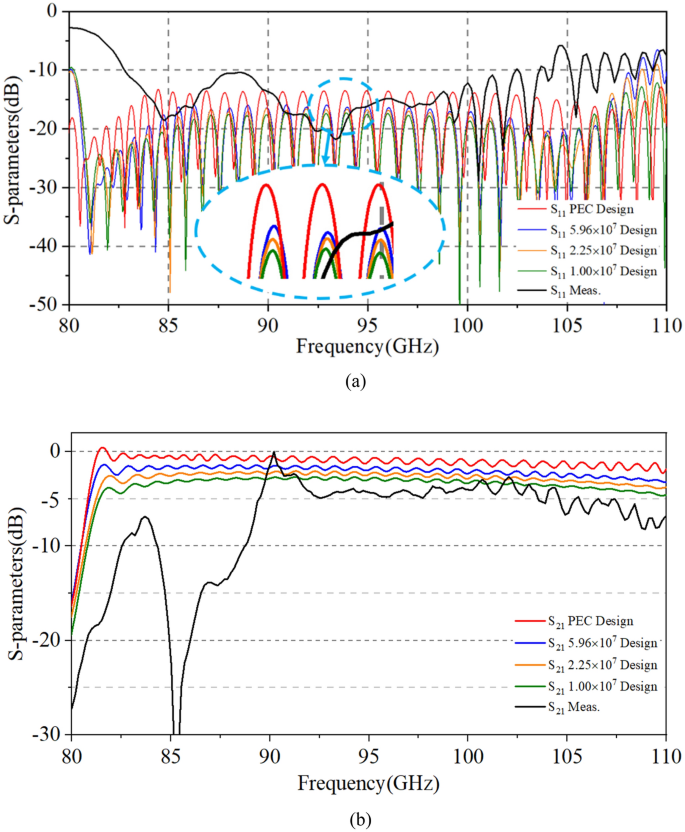
Effects of conductivity on return loss ( a ) and transmission loss ( b ). ( a ) We take the conductivity of PEC as + ∞. The simulation results of S 11 from top to bottom are + ∞, 5.96 × 10 7 , 2.25 × 10 7 , 1.00 × 10 7 , respectively.
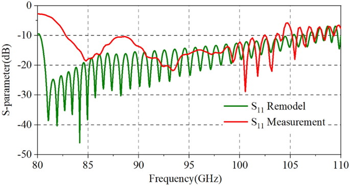
Effects of surface roughness of the SWS ports on return loss.
Beam-wave interaction simulation results and analyses
To investigate the beam-wave interaction and amplification characteristics of our new double-mode two-stage multiple pencil beam SDV-TWT, we conducted a 3D PIC simulation by using CST 27 , 28 . At this time, we set background materials to oxygen-free copper whose conductivity is 2.25 × 10 7 S/m. The settings of each port and the injection structure of the electron beam are shown in Fig. 6 where the radius of pencil electron beams is br = 0.12 mm with a filling ration of 44% (the radius of tunnels is tr = 0.18 mm).
Each average current of three pencil electron beams is set as 0.15A with a corresponding current density of 309A/cm 2 , the operation voltage is 22.1 kV and the uniform axial focusing magnetic field is 0.5 T. We set the input power of driving sinusoidal signal at 94 GHz as 0.12 W. We have optimized and adjusted the input power, the output power and gain obtained are saturated as is shown in Fig. 13 a. It costs about a week to finish this continuous simulation for one frequency, until 120 ns at a single frequency of 94 GHz with extremely output stability.
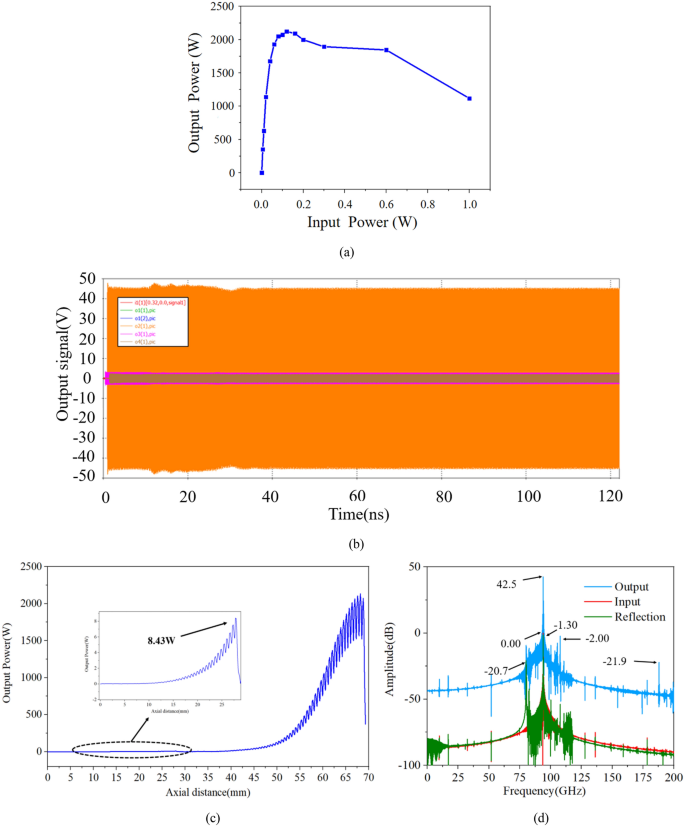
( a ) Input power versus output power. ( b ) The output signal of the PIC simulation at 94 GHz. The max voltage of output signal is about 46 V, so the output power is over 2120 W with a 0.12 W input power corresponding to a 42.5 dB gain. ( c ) The growth rate of whole SWS. Maximum power reaches 8.43 W before the attenuator then falls, and the growth rate of whole structure is 0.62 dB/mm corresponding to 0.83 dB/period. ( d ) Frequency spectra of the input, reflection and output signal.
As is shown in Figs. 13 b,c the 0.12 W input signal is amplified to a 120 ns steady 2120 W output peak signal with a gain of 42.5 dB, an electron efficiency of 10.7% and a growth rate of nearly 0.62 dB/mm, while the power of reflection signal keeps below 0.37 W. It is less than that of the input signal during the whole simulation time. Figure 13 d shows the frequency spectrum results, we can see that the maximum monochromatic output signal peaks at 94 GHz which is 42.5 dB higher than that of the input signal while the reflection signal is -1.30 dB lower than that of the input signal which proves that no oscillations are generated. Based on Pierce theory, we know that as the interaction impedance improves the interaction efficiency increases and our multiple pencil beam TWT can get a 10.7% electron efficiency which is much higher than that of sheet beam TWT (5.4%) and single pencil beam TWT (2.8%), so we can get a higher output peak power and a higher growth rate SDV TWT. Besides, compared to the sheet beam SWS (119.4 mm length 19 ) and the single pencil beam TWT (102.3 mm length 15 ), our multiple pencil beam SWS does not need complicated coupler which means it can not only make the whole structure shorter (70.3 mm) but also reduce the problems of fabrication.
The phase space plot of the bunched electron beam at 50 ns is shown in Fig. 14 a. With initial electron energy of 22 keV, the highest increases to ~ 24.8 keV while the lowest decreases to ~ 18.2 keV at the end of the SWS which means most of the particles have lost energy that amplified the RF signal. We set particles’ position monitor to observe the inset of electron cluster diagram from 3 to 50 ns which is about the same as is shown in Fig. 14 a where the electron beam bunches very well rather than intercepting on the wall at the end of the SWS. So, we can conclude that our TWT can operate steadily during the 50 ns long simulation time.
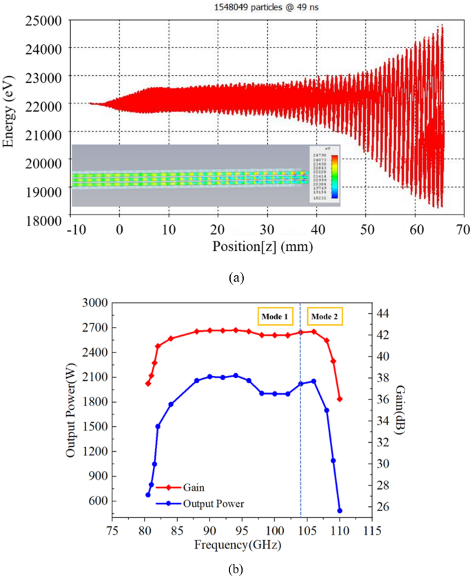
( a ) Phase space plot of the bunched electron beam at 50 ns. The lower left inset is the electron bunching at the end of the SWS at 50 ns. ( b ) Output power and gain versus frequency.
By sweeping the frequency from 80 to 110 GHz with 18 integral frequencies, which is a long-time simulation (each frequency point should be calculated for one weeks), we obtain the output power–frequency and gain-frequency response of our high-power double-mode two-stage TWT as shown in Fig. 14 b. We can see that the 3 dB bandwidth of about 29 GHz (81 GHz to 110 GHz) can be achieved. It is two modes (mode 1 from 81-103 GHz and mode 2 from 104-110 GHz) which could interact with the same energy electron particles obviously; compared to our previous work, the bandwidth in this paper is indeed expanded from 15 to 29 GHz, which is nearly twice than before 11 . It implies that when the TWT operates at the fundamental double modes rather than in the fundamental one mode, the beam-wave interaction bandwidth could be increased undoubtedly. The TWT we designed has a certain input signal. It could be possible to generate mode competitions and oscillations in TWT. But under the influence of the input signal and beam-wave interaction, the competitions at other frequencies and other modes are suppressed successfully, only signals of the same frequency as the input signal are amplified. As our hot simulation, there is no oscillation with the stable amplified output signals of each frequency from 80–110 GHz. The simulation results show that the output signal is stable and the frequency spectrum is pure, which means the oscillations are suppressed in our TWT. Thus, our double-mode two-stage a planar alignment plan alignment multiple-beam SDV-TWT can be used as the new scheme for the ultra-wide band and high output power in the millimeter and terahertz band in the future.
This paper presents a thorough design, fabrication and analysis of a double-mode two-stage planar alignment three-pencil beam staggered double vane circuit in W-band. The simulation results show that it indeed has an ultra-wide beam-wave matching band and a very high interaction impedance. Two-stage SDV-SWS structure and an attenuator between two sections are adopted to suppress reflection and oscillation, and a simple input/output coupler without any taper is designed to get a high transmission performance. The cold test results of manufacturing SDV-SWS show that this TWT indeed can promote bandwidth as much as simulation results. 3D PIC simulation results predict that at 94 GHz our TWT can achieve a peak output power of 2120 W, a peak gain of 42.5 dB and an electron efficiency of 10.7% with a very short length of about 70 mm, and simultaneously can get a 3 dB bandwidth of 29 GHz. Anyway, the important thing is, the adoption of double-mode with matching of the same electron beam can indeed increase bandwidth, and the multiple pencil beam SDV-SWS can enhance the output power, gain, and growth rate in some extends. Also, the investigation of electron gun and optics system for such planar alignment three pencil beam have been performed by our group recently 29 . Such good ideas as double-mode and planar alignment multiple pencil beam have been used at the high terahertz band, e.g. 220 GHz and 340 GHz, some initial good results with simulation have been obtained for such schemes, and the ultra-wideband and high output can be achieved with SDV-TWT 13 , 14 . Therefore, it really has great potentials and values in our follow-up work at terahertz band in future.
Yu, X. et al. Waveguide-input resonant tunnelling diode mixer for THz communications. Electron. Lett. 56 , 342–344 (2020).
Article ADS Google Scholar
Liao, W. et al . A Ka-band active integrated antenna for 5g applications: initial design flow. In 2018 2 nd URSI Atlantic Radio Science Meeting (AT-RASC), Meloneras , 1–4 (2018).
Jain, R. et al . 29.1 A 0.42THz 9.2dBm 64-pixel source-array SoC with spatial modulation diversity for computational terahertz imaging. In 2020 IEEE International Solid-State Circuits Conference - (ISSCC) , San Francisco, CA, USA, 440–442 (2020).
Baig, A. et al. Performance of a nano-CNC machined 220-GHz travelling wave tube amplifier. IEEE Trans. Electron Dev. 64 , 590–592 (2017).
Article Google Scholar
Duan, Z. et al . Experimental advances in 220 GHz sheet-beam travelling-wave tubes. In 2019 44th International Conference on Infrared, Millimeter, and Terahertz Waves (IRMMW-THz), Paris, France, 1–2 (2019).
Rakesh, R. S. et al . Design & simulation of coaxial couplers for X-band TWT. In Proceedings of 2nd International Conference Electronics, Communication and Aerospace Technology (ICECA) , 395–398 (2018).
Ruan, C., Zhan, M. & Liang, H. Investigation on ultra-wide band plan alignment multiple beam W-band travelling wave tube with two stage staggered double-vane structure. In 2016 41st International Conference on Infrared, Millimeter, and Terahertz waves (IRMMW-THz) , Copenhagen, 1–2 (2016).
Bai, N. et al. A Ka-band folded waveguide travelling wave tube with lumped resistance metamaterial absorber. IEEE Trans. Electron Dev. 67 , 1248–1253 (2020).
Article ADS CAS Google Scholar
Fang, S. et al. Experimental verification of the low transmission loss of a flat-roofed sine waveguide slow-wave structure. IEEE Electron Dev. Lett. 40 , 808–811 (2019).
Zhang, C. & Ruan, C. Investigation of W-band high power TWT amplifier with broadband output window. In 2019 Photonics & Electromagnetics Research Symposium - Fall (PIERS - Fall) , Xiamen, China, 560–565 (2019).
Ruan, C. et al. W-band multiple beam staggered double-vane travelling wave tube with broad band and high output power. IEEE Trans. Plasma Sci. 43 , 2132–2139 (2015).
Tian, H. et al. 3-D fast nonlinear simulation for beam-wave interaction of sheet beam travelling-wave tube. IEEE Trans. Electron Dev. 66 , 1504–1511 (2019).
Ruan, C. & Zhan, M. Design of a G-Band sheet electron beam travelling wave tube. In International Vacuum Electron Conference (IVEC) , Monterey, CA, 1–2 (2016).
Ruan, C. et al . Investigation on stability of the beam-wave interactions for g-band staggered double vane TWT. In 2018 43rd International Conference on Infrared, Millimeter, and Terahertz Waves (IRMMW-THz) , Nagoya, 1–2 (2018).
Lai, J. et al. W-band 1-kW staggered double-vane traveling-wave tube. IEEE Trans. Electron Dev. 59 , 496–503 (2012).
Shin, Y., Barnett, L. R. & Luhmann, N. C. Phase-shifted travelling-wave-tube circuit for ultrawideband high-power submillimeter-wave generation. IEEE Trans. Electron Dev. 56 , 706–712 (2009).
Borsuk, G. M. & Levush, B. PL-2: vacuum electronics research perspective at the naval research laboratory. In IEEE International Vacuum Electron Conference (IVEC) , Monterey, CA, 3–4 (2010).
Shin, Y. et al. Numerical modeling analysis of 0.22 THz sheet beam TWT circuit. In International Vacuum Electron Conference (IVEC), Bangalore, 139–140 (2011).
Lai, J. et al. A staggered double vane circuit for a W-band travelling-wave tube amplifier. Chin. Phys. B 21 (6), 0684031–0684036 (2012).
Shin, Y. et al. System design analysis of a 0.22-THz sheet-beam traveling-wave tube amplifier. IEEE Trans. Electron Dev. 59 , 234–240 (2012).
Kory, C. L. et al. Design of overmoded interaction circuit for 1-kW 95-GHz TWT. IEEE Trans. Electron Dev. 56 , 713–720 (2009).
Tucek, J. et al. 220 GHz folded waveguide circuits for high power amplifiers. In International Vacuum Electron Conference (IVEC) , Rome, Italy, April 108–109 (2009).
Malekabadi, A. & Paoloni, C. UV-LIGA microfabrication process for sub-terahertz waveguides utilizing multiple layered SU-8 photoresist. J. Micromech. Microeng. 26 , 095010 (2016).
Gamzina, D. & Ravani, B. Thermomechanical fatigue in sub-THz vacuum electron devices. IEEE Trans. Electron Dev. 63 , 4948–4954 (2016).
Gamzina, D., Luhmann, N. C. & Ravani, B. Thermo-mechanical stress in high-frequency vacuum electron devices. J. Infr. Millim. Terahertz Waves 38 , 47–61 (2017).
Stockwell, B. C. et al . P4-2: Permanent magnet for HiFIVE sheet beam transport. In International Vacuum Electron Conference (IVEC) , 451–452 (2010).
CST PS Tutorial, CST Corp. https://www.cstchina.cn/ .
CST Particle Studio SUITE User Manual, CST AG, Darmstadt, Germany (2012).
Zhang, H. & Ruan, C. Design of the planar distributed three-beam gun for W-band staggered double vane TWT. In 2018 IEEE International Vacuum Electronics Conference (IVEC) , Monterey, CA, 353–354 (2018).
Download references
Acknowledgements
This work was supported by the National Natural Science Foundation of China (Grant No. 61831001).
Author information
Authors and affiliations.
School of Electronic and Information Engineering, Beihang University, Beijing, 100191, China
Zheng Zhang, Cunjun Ruan, Ayesha Kosar Fahad, Chenyu Zhang, Yiyang Su & Pengpeng Wang
Beijing Key Laboratory for Microwave Sensing and Security Applications, Beihang University, Beijing, 100191, China
Cunjun Ruan
College of Electronics and Information Engineering, Shenzhen University, Shenzhen, 518061, China
You can also search for this author in PubMed Google Scholar
Contributions
C.R. initiated and charged the research project. Z.Z. conducted the model design and CST simulations, Z.Z., Z.C. and P.W. were responsible for drawing and processing the physical model, Z.Z. finished the cold test, A.K.F., W.H. and Y.S. contributed to the discussions and manuscript revision.
Corresponding author
Correspondence to Cunjun Ruan .
Ethics declarations
Competing interests.
The authors declare no competing interests.
Additional information
Publisher's note.
Springer Nature remains neutral with regard to jurisdictional claims in published maps and institutional affiliations.
Rights and permissions
Open Access This article is licensed under a Creative Commons Attribution 4.0 International License, which permits use, sharing, adaptation, distribution and reproduction in any medium or format, as long as you give appropriate credit to the original author(s) and the source, provide a link to the Creative Commons licence, and indicate if changes were made. The images or other third party material in this article are included in the article's Creative Commons licence, unless indicated otherwise in a credit line to the material. If material is not included in the article's Creative Commons licence and your intended use is not permitted by statutory regulation or exceeds the permitted use, you will need to obtain permission directly from the copyright holder. To view a copy of this licence, visit http://creativecommons.org/licenses/by/4.0/ .
Reprints and permissions
About this article
Cite this article.
Zhang, Z., Ruan, C., Fahad, A.K. et al. Multiple-beam and double-mode staggered double vane travelling wave tube with ultra-wide band. Sci Rep 10 , 20159 (2020). https://doi.org/10.1038/s41598-020-77204-w
Download citation
Received : 15 July 2020
Accepted : 12 October 2020
Published : 19 November 2020
DOI : https://doi.org/10.1038/s41598-020-77204-w
Share this article
Anyone you share the following link with will be able to read this content:
Sorry, a shareable link is not currently available for this article.
Provided by the Springer Nature SharedIt content-sharing initiative
This article is cited by
Scientific Reports (2022)
By submitting a comment you agree to abide by our Terms and Community Guidelines . If you find something abusive or that does not comply with our terms or guidelines please flag it as inappropriate.
Quick links
- Explore articles by subject
- Guide to authors
- Editorial policies
Sign up for the Nature Briefing newsletter — what matters in science, free to your inbox daily.
Microwave Tubes as Microwave Source (Oscillators) and Amplifiers
- First Online: 21 June 2018
Cite this chapter

- Prakash Kumar Chaturvedi 2
2935 Accesses
1 Citations
A source of microwave power is essential for any microwave system. All communication and radar system generally use high power in kW range (CW or pulsed) for the transmitter and a few low-power sources for local oscillator/down conversion.
This is a preview of subscription content, log in via an institution to check access.
Access this chapter
- Available as PDF
- Read on any device
- Instant download
- Own it forever
- Available as EPUB and PDF
- Compact, lightweight edition
- Dispatched in 3 to 5 business days
- Free shipping worldwide - see info
- Durable hardcover edition
Tax calculation will be finalised at checkout
Purchases are for personal use only
Institutional subscriptions
Author information
Authors and affiliations.
Department of Electronics & Communication Engineering, SRM University, NCR Campus, Ghaziabad, Uttar Pradesh, India
Prakash Kumar Chaturvedi
You can also search for this author in PubMed Google Scholar
Corresponding author
Correspondence to Prakash Kumar Chaturvedi .
Rights and permissions
Reprints and permissions
Copyright information
© 2018 Springer Nature Singapore Pte Ltd.
About this chapter
Chaturvedi, P.K. (2018). Microwave Tubes as Microwave Source (Oscillators) and Amplifiers. In: Microwave, Radar & RF Engineering. Springer, Singapore. https://doi.org/10.1007/978-981-10-7965-8_5
Download citation
DOI : https://doi.org/10.1007/978-981-10-7965-8_5
Published : 21 June 2018
Publisher Name : Springer, Singapore
Print ISBN : 978-981-10-7964-1
Online ISBN : 978-981-10-7965-8
eBook Packages : Engineering Engineering (R0)
Share this chapter
Anyone you share the following link with will be able to read this content:
Sorry, a shareable link is not currently available for this article.
Provided by the Springer Nature SharedIt content-sharing initiative
- Publish with us
Policies and ethics
- Find a journal
- Track your research
- Google News

Advertisement
- Technical Articles
The Travelling Wave Tube (TWT) – A Vacuum Tube Still Key to Microwave Amplification
TWT (Travelling Wave Tube) comes from the close interaction between an electron wave and the RF signal to be amplified
Earlier this year, the James-Webb Space Telescope sent back to Earth some of the most detailed images of other galaxies. This was partly due to a Vacuum Electronics Device (VED) called the Travelling Wave Tube Amplifier (TWTA), which was part of the microwave amplification system used on the telescope and the ground station. TWTs have a history going back over 80 years, before WWII. Some brilliant RF engineering pioneers such as Haeff, Lindenblad, Kompfner and others are credited with the invention and improvement of this device back in the 1930s and 1940s. However, it was during peace times, post WWII that the usage of TWTs increased dramatically. They were used for creating microwave ground relay stations and on communication satellites such as Telstar, Intelsat, Inmarsat etc., and helped create the global communication networks we are used to today.
TWT is also used on all deep space probe missions such as Voyager and Cassini. Today there are thousands of TWTs in orbit, as well as in satellite ground stations. TWTs are also widely used in electronic warfare, such as guidance systems as well as radar systems. Thales, Stellent, NEC, Teledyne e2V and others are the dominant providers. Current estimates put the market value for TWTA’s at around $1B, with a low single-digit annualized growth rate.
Operation Principle of TWT
The beauty of the TWT comes from the close interaction between an electron wave and the RF signal to be amplified. A simplified view of one of the common versions of this device called the Helix TWT is shown in Figure 1.

The electron wave is generated in an electron source consisting of a heated cathode, with temperatures reaching around 1000oC. An Ultra High Vacuum (<10-8 Torr) is present in the tube. An HV, typically 4-120 kV applied between the anode and cathode, creates the beam, while a focus or control grid helps guide the beam into the next part of the device. An Electronic Power Conditioner (EPC) converts the satellite bus voltage to provide the regulated HV needed for the electron source. The Slow Wave Structure (SWS) is where the RF input wave is slowed down using the Helix as a delay line, with the goal being to match the wave velocities of the electron beam and the RF wave. A periodic permanent magnet in the SWS focuses the electron beam toward the device axis.

Velocity modulation of the electron beam, as it interacts with the helix, creates electron bunching and a positive feedback mechanism with amplification of the RF wave as momentum lost from the electron beam is transferred to the RF wave through the principle of momentum conservation. The helix provides a low impedance path for the RF wave and may be composed of low O2 Cu, for example. Attenuators that prevent oscillations and reflections can separate various helix sections and maintain wave stability.
3D Electromagnetic simulations can be used to optimize the cavity and helix; for example, the pitch of the helix can vary along the tube length to match the electron wave velocity change. Ceramic rods, for example, made of BeO can support the helix and provide heat transfer. The last stage is the collector, which absorbs the remaining electron energy and converts it to heat. Creating a multi-stage depressed collector makes it possible to recover a lot of the electron energy and improve overall efficiency. An Example RF output vs. input curves is shown in Figure 2a.

The device has a linear range where most small signal amplification could be done with low distortion. An Output Back Off (OBO) is used to operate the device below its saturated power level, and C/3IM shows the S/N to the 3rd harmonic wave. Figure 2b shows an example plot of efficiency and power vs frequency for a Ku-band TWTA. Linearizers can be used with the TWT, as shown in Figure1, which shows a Linearizer Channel Amplifier (LCAMP). LCAMPs include a digital or hardware pre-distorter that can adjust the RF input, compensating for the tube’s non-linearity, to provide either a constant gain or output level. Table 1 shows some of the basic specifications from TWTA’s provided by one of the manufacturers at the Ku and Q frequency bands.

The manufacture of space TWTA’s is a precision handcraft process that can take several months and requires tuning cycles at room temperature and hot and cold temperatures. Costs can range from several thousand to hundreds of thousands of dollars per TWTA.
Advantages of TWTA and comparisons to Solid State Power Amplifiers (SSPA)
One of the most useful features of TWTA’s that led to its widespread use early on is its high bandwidth (BW) and low noise figure. As opposed to resonant VEDs such as Klystrons, which have limited BW and are sensitive to structural spacing, the TWTA’s provide higher BW (typically exceeding 2 octaves) at frequencies ranging from 300MHz to several 100 GHz, high gains (up to 70db) and peak powers that can range from 10’s of W to several 1000’s of kWs. Compared to Helix TWTA’s, Coupled cavity TWTA’s are a version that can provide higher power with lower BW. In recent years, SSPA, particularly GaN-based ones, have replaced TWTA’s in some of the traditional TWTA application space. Microwave relay stations, Low Earth Orbit satellites, such as OneWebTM, now rely mostly on SSPA. Table 2 provides a comparison between the TWTA and SSPA.

SSPA’s can provide a lower size, weight and cost advantage and dominates usage in the C-band Band [1], with accelerated usage at higher bands like Ku/Ka, but with TWTA’s still dominating this higher frequency space. SSPA’s can provide better linearity than TWTA’s [2]. Disadvantages of SSPA, however, include large heat generation and the complexity involved in paralleling multiple devices, especially at the higher power/frequency space, along with decreasing efficiencies in this space. TWTAs can have conduction or radiation cooling and are much more stable at high temperatures. A study in 2007 [3] estimated that 69% of all Geo-Stationary Satellites exclusively used TWTA’s, with 24% using a hybrid TWTA/SSPA combination. Figure 3 shows a Power/Frequency usage space for the SSPA and TWTA. Both devices are extending their usage envelope.

There are several innovations that will ensure TWTA usage far into the future, some of which are listed below:
- Extension to Q/V and W bands: Satellite communication networks aim to provide “Terabit Connectivity” with High Throughput Satellites (HTS). To facilitate this, the frequency will be increased from the current Ku/Ka bands (20/30 GHz) to the Q/V bands (50GHz for uplink and 40 GHz for downlink) [4]. Several manufacturers, such as NEC [5] have demonstrated TWTs in this frequency space. Further out in frequency, the European Commission H2020 TWEETHER project plans to use the W band (92-95 GHz) for point-to-multipoint transmission hubs and TWTs are planned for this [6].
- Mini-TWTs: These are smaller versions, with lengths as small as 7 inches and are typically integrated with SSPA amplifiers to work as the final gain stage in a Microwave Power Module (MPM) . These much lighter mini-TWTs typically work at lower cathode voltages (< 8kV) and current densities (<3A/cm2) to provide better lifetimes. The SSPA preamplifier compensates for lower gains from the TWT. Such MPMs have been used, for example in pulsed phased array radar systems [7]
- Flex-TWTs: The goal here is to make the TWTs remote-controlled from ground stations to vary frequency and power levels. Power level control through anode voltage changes and frequency modulation through the helix and collector voltage change has been demonstrated [8].
[1] W. Lohmeyer, et al., “Communication satellite power amplifiers: current and future SSPA and TWTA technologies”, International Journal of Satellite Communications and Networking, 2015
[2] X. Jing, et.al, “A Comparison of SSPA and TWTA for Beidou Navigation Satellite Systems”, 2021 Int. Conf. Microwave and Millimeter Wave Technologies
[3] K. P. Mallon, “TWTAs for satellite communications: past, present, and future”, IEEE Int. Vacuum Electronics Conf., 2008
[4] G. Codispoti, et. al., “Validation of ground technologies for future Q/V band satellite systems: the QV-LIFT project,” IEEE Aerospace Conf., 2018
[5] N. Kosugi, et. al., “NEC Network and Sensor Systems Ltd Q/V Band Helix TWT for Future High Throughput Satellite Uplink Applications,” 2020 IEEE 21 st Int. Conf. Vacuum Electronics
[6] F. Andre, et. al., “W-band TWT for High Capacity Transmission Hub for Small Cells Backhaul,” 2018 IEEE Int. Vacuum Electronics Conference
[7] T. Muhehiro, et. al., “Development of an X-band 800W Pulsed Mini-TWT for Active Phased Array Radar Modules,” 2014 IEEE Int. Vacuum Electrons Conference
[8] E. Cuignet, et. al., “Very High efficiency Dual Flexible TWTA, a flexible concept allowing to deal with performances and schedule constraints of telecommunications Payloads,” 2013 IEEE Int. Vacuum Electrons Conference

Share this:
- Click to share on X (Opens in new window)
- Click to share on Facebook (Opens in new window)
- Click to share on LinkedIn (Opens in new window)
- Click to share on WhatsApp (Opens in new window)
- Click to share on Telegram (Opens in new window)
Towards Sustainable Electric Mobility: Addressing Carbon Emissions Across the Value Chain
Addionics, il science forge partnership to propel next-gen lithium-metal batteries, improving short-circuit withstand time in gan hemt power devices, leave a reply cancel reply.
Your email address will not be published. Required fields are marked *
Notify me of follow-up comments by email.
Notify me of new posts by email.
Collective Variable Model for the Analysis of Traveling-Wave Tube
Ieee account.
- Change Username/Password
- Update Address
Purchase Details
- Payment Options
- Order History
- View Purchased Documents
Profile Information
- Communications Preferences
- Profession and Education
- Technical Interests
- US & Canada: +1 800 678 4333
- Worldwide: +1 732 981 0060
- Contact & Support
- About IEEE Xplore
- Accessibility
- Terms of Use
- Nondiscrimination Policy
- Privacy & Opting Out of Cookies
A not-for-profit organization, IEEE is the world's largest technical professional organization dedicated to advancing technology for the benefit of humanity. © Copyright 2024 IEEE - All rights reserved. Use of this web site signifies your agreement to the terms and conditions.

- Microwave Engineering Tutorial
- Microwave Engineering - Home
- Introduction
- Transmission Lines
- Modes of Propagation
- Types of Transmission Lines
- Avalanche Transit Time Devices
- Microwave Devices
- E-Plane Tee
- H-Plane Tee
- E-H Plane Tee
- Rat-race Junction
- Directional Couplers
- Cavity Klystron
- Reflex Klystron
Travelling Wave Tube
- Measurement Devices
- Measurements
- Example Problems
- Microwave Engineering Resources
- Quick Guide
- Microwave Engineering - Resources
- Microwave Engineering - Discussion
- Selected Reading
- UPSC IAS Exams Notes
- Developer's Best Practices
- Questions and Answers
- Effective Resume Writing
- HR Interview Questions
- Computer Glossary
Travelling wave tubes are broadband microwave devices which have no cavity resonators like Klystrons. Amplification is done through the prolonged interaction between an electron beam and Radio Frequency (RF) field.
Construction of Travelling Wave Tube
Travelling wave tube is a cylindrical structure which contains an electron gun from a cathode tube. It has anode plates, helix and a collector. RF input is sent to one end of the helix and the output is drawn from the other end of the helix.
An electron gun focusses an electron beam with the velocity of light. A magnetic field guides the beam to focus, without scattering. The RF field also propagates with the velocity of light which is retarded by a helix. Helix acts as a slow wave structure. Applied RF field propagated in helix, produces an electric field at the center of the helix.
The resultant electric field due to applied RF signal, travels with the velocity of light multiplied by the ratio of helix pitch to helix circumference. The velocity of electron beam, travelling through the helix, induces energy to the RF waves on the helix.
The following figure explains the constructional features of a travelling wave tube.
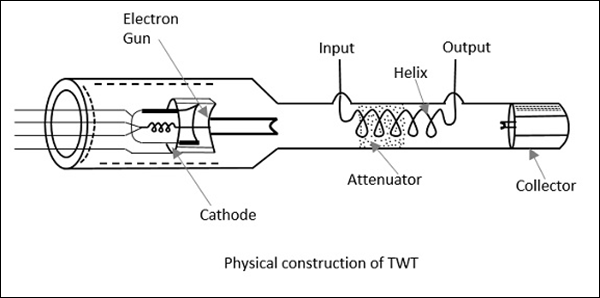
Thus, the amplified output is obtained at the output of TWT. The axial phase velocity $V_p$ is represented as
$$V_p = V_c \left ( {Pitch}/{2\pi r} \right )$$
Where r is the radius of the helix. As the helix provides least change in $V_p$ phase velocity, it is preferred over other slow wave structures for TWT. In TWT, the electron gun focuses the electron beam, in the gap between the anode plates, to the helix, which is then collected at the collector. The following figure explains the electrode arrangements in a travelling wave tube.
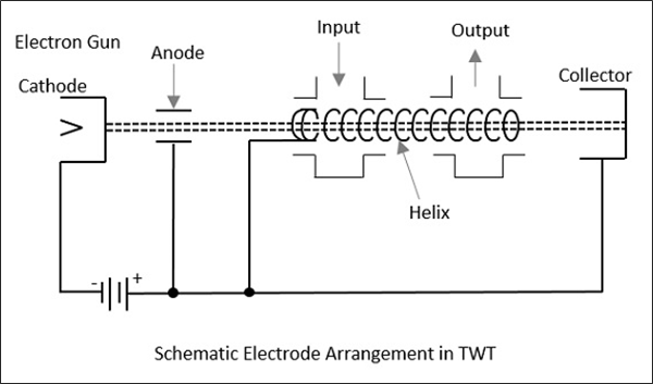
Operation of Travelling Wave Tube
The anode plates, when at zero potential, which means when the axial electric field is at a node, the electron beam velocity remains unaffected. When the wave on the axial electric field is at positive antinode, the electron from the electron beam moves in the opposite direction. This electron being accelerated, tries to catch up with the late electron, which encounters the node of the RF axial field.
At the point, where the RF axial field is at negative antinode, the electron referred earlier, tries to overtake due to the negative field effect. The electrons receive modulated velocity. As a cumulative result, a second wave is induced in the helix. The output becomes larger than the input and results in amplification.
Applications of Travelling Wave Tube
There are many applications of a travelling wave tube.
TWT is used in microwave receivers as a low noise RF amplifier.
TWTs are also used in wide-band communication links and co-axial cables as repeater amplifiers or intermediate amplifiers to amplify low signals.
TWTs have a long tube life, due to which they are used as power output tubes in communication satellites.
Continuous wave high power TWTs are used in Troposcatter links, because of large power and large bandwidths, to scatter to large distances.
TWTs are used in high power pulsed radars and ground based radars.
To Continue Learning Please Login

IMAGES
VIDEO
COMMENTS
The traveling-wave tube (TWT), also known as the traveling-wave amplifier (TWA) or traveling-wave tube amplifier (TWTA), is a widely used amplifier in satellite communications and radar. ... Eventually, as more bunching occurs, the space-charge forces of the beam will cause the electron bunches in the beam to de-bunch. ... In the process of ...
Theory of Operation pg. 2. In normal operation, an RF signal introduced at the cathode end of the helix travels along the circum-ference of the helix at approximately the velocity of light, although the velocity in the direction of the beam is reduced by the pitch-to-circumference ratio of the helix. When the voltage on the helix is properly ...
A travelling wave tube is a high power amplifier used for the amplification of microwave signals up to a wide range. It is a special type of vacuum tube that offers an operating frequency ranging between 300 MHz to 50 GHz.. Travelling wave tubes are non-resonant structures that offer continuous interaction of applied RF field with the electron beam over the entire length of the tube.
Bunching takes place in the Traveling Wave Tube Working through a process that is a cross between those of the multicavity klystron and the magnetron. Electrons leaving the cathode at random quickly encounter the weak axial RF field at the input end of the helix, which - is due to the input signal.
Traveling wave tubes are rapidly evolving to provide unprecedented power level in comparison to solid state devices in the millimeter waves region of the spectrum (80-300 GHz) thus enabling a wide range of applications. ... As the field amplitude increases, the bunching process becomes stronger leading to a reinforcement in wave amplitude and ...
Summary. In a klystron a linear electron beam is modulated by the r.f. field of the gap in the input cavity resonator. The modulation is increased by interaction with the fields of a succession of bunching cavities and r.f. power extracted by interaction with the field of an output cavity. The small-signal theory and large-signal behaviour of ...
The travelling-wave tube, though structurally simple, is a *Con-structed Complication*. Because of its structural simplicity, TWTs have been built to operate at frequencies as high as 50 GHz. Modern require-ments for TWr amplifiers often call for very wide bandwidths combined with high power output.
A traveling-wave tube ( TWT, pronounced "twit" [1]) or traveling-wave tube amplifier ( TWTA, pronounced "tweeta") is a specialized vacuum tube that is used in electronics to amplify radio frequency (RF) signals in the microwave range. [2] It was invented by Andrei Haeff around 1933 as a graduate student at Caltech, and its present form was ...
The interaction of the electron beam in a folded waveguide with the signal produces high density aggregations of electrons, called bunches, that being retard...
In such a set-up, the traveling wave gains energy at the expense of the kinetic energy of the electron beam. This continuous interaction and subsequent ampli fication of the electromagnetic wave happens over a distance(the length of the interaction region of the TWTuntil the ) ampli ed wave is extracted at the output. fi.
I'm having a bit of trouble finding a good source to understand how exactly a traveling wave tube amplifier works. I understand the basic premise that the electron beam gives up kinetic energy to the traveling wave, but I'm having a bit of trouble understanding how this actually happens.. The first type of explanation (such as this one) that I've found indicates that the electric field of the ...
A t th is an interna l vo lum e of -6 0 .025 literwou ld leak rate, the pressure in a dorm ant TW Tw ith at standard tem perature and pressure). A t th is. 1- -long pore. (1 torr- OLWH U VHF§ FP /sec leak rate of about 10. 3 torr-liters/sec for a Thus, pore leakage is un like ly to occur be low a.
The Traveling Wave Tube (twt) is a high-gain, low-noise, wide-bandwidth microwave amplifier. It is capable of gains greater than 40 dB with bandwidths exceeding an octave. (A bandwidth of 1 octave is one in which the upper frequency is twice the lower frequency.) Traveling-wave tubes
Perhaps the most successful microwave and millimeter wave amplifier has been the traveling wave tube (TWT). In traveling-wave tubes (TWTs), the electron stream moves in the field of a traveling electromagnetic wave whose phase velocity is slowed to the beam velocity by e.g. helices, coupled cavities, or ring bar and ring loop.
This paper presents design, fabrication and cold test of an ultra-wide band travelling wave tube (TWT) with planar alignment multiple pencil beams. The fundamental double-mode of staggered double ...
VII. TRAVELING-WAVE TUBES L.D.Smullin P.M.Lally Prof. L.J.Chu C.Rowe L.A.Harris F.Tofalo A.A.Karp A. THREE-CM TRAVELING-WAVE AMPLIFIER TUBES 1. Helix Studies As mentioned in the last Progress Report, a large-scale model of the helix used in the traveling-wave tube was constructed. The phase velocities
The bunching process: ... 5.6 Travelling Wave Tube Amplifier (TWTA) The TWTA was invented in 1944 by Kompfner, when he felt that in two-cavity klystron, full energy of the electron is not getting transferred to the microwave signal in the cavity for amplification, due to interaction in electron beam and RF field being only in the cavity. ...
The Travelling Wave Tube (TWT) - A Vacuum Tube Still Key to Microwave Amplification. TWT (Travelling Wave Tube) comes from the close interaction between an electron wave and the RF signal to be amplified. Earlier this year, the James-Webb Space Telescope sent back to Earth some of the most detailed images of other galaxies.
Bunching process: The Electrons from the bunching centre they pass through at Vs=0 with an unchanged velocity Vo.During the Positive half cycles of the microwave input voltage ... Traveling wave tubes (TWT) are wideband amplifiers. They take therefore a special position under the velocity-modulated tubes. One reason of the special low-noise
Traveling-wave tube (TWT) is an important kind of high-power microwave/terahertz source. The physical mechanism of the inherent nonlinear beam-wave interaction process in TWT should be accurately investigated for fast and accurate design. Conventional treatment involves a large amount of computation and is thus time-consuming. In this article, we propose a novel method to expound the ...
Construction of Travelling Wave Tube. Travelling wave tube is a cylindrical structure which contains an electron gun from a cathode tube. It has anode plates, helix and a collector. RF input is sent to one end of the helix and the output is drawn from the other end of the helix. An electron gun focusses an electron beam with the velocity of light.
This process is called velocity modulation. If the electrons of the beam were accelerated to travel faster than the waves traveling on the wire, electron bunching would occur through the effect of velocity modulation. (see Figure 4) By delivering energy to the electron beam, the power of the traveling wave decreases.
A traveling-wave tube (TWT) is a specialized vacuum tube that is used in electronics to amplify radio frequency (RF) signals in the microwave range.[1] ... By the time it reaches the other end of the tube, this process has had time to deposit considerable energy back into the helix. A second directional coupler, positioned near the collector ...