- Tekonsha Manuals
- Electronic Brake Control
- Installation manual

Tekonsha Electronic Brake Control Installation Manual
- User manual
- page of 2 Go / 2
Advertisement
Quick Links
Related manuals for tekonsha electronic brake control.

Summary of Contents for Tekonsha Electronic Brake Control
- Page 1 ✓ Electronic Brake Control Installation Guide Leveling the Sensor If trailer brakes lock up: ❑ Turn power down using power knob. For 2, 4, 6* and 8* brake applications After the brake control has been securely mounted WARNING The Brake Control must be mount- (Rotate power knob toward the 8 o’clock...
- Page 2 Troubleshooting Chart NOTE: Always warm the trailer's brakes before Situation Probable Cause setting the power. Warm trailer brakes tend Tow vehicle connected to trailer, 1. Corrosion on trailer plug contact. to be more responsive than cold brakes. To NO GREEN light. 2.
Rename the bookmark
Delete bookmark, delete from my manuals, upload manual.
Tekonsha Voyager Brake Controller Wiring Diagram
Braking your trailer can be a daunting task, especially when you hit those undiscovered roads. But with the Tekonsha Voyager Brake Controller Wiring Diagram, you can make sure your braking system is running as smoothly as possible. This guide walks through every step of your brake controller installation, from selecting the right wires to connecting them to the correct terminals. The wiring diagram provides a comprehensive overview of your trailer's electrical system including voltage, current, amperage and more. Plus, it features reliable diagrams that illustrate exactly how each wire should be connected, saving you time and energy. Not only does the wiring diagram make your controller installation a breeze, but it also helps streamline maintenance tasks. With it, you can troubleshoot problems quickly and get back on the road in no time. This ensures that you’ll always have reliable brakes when you need them, even when you’re hauling something heavy. Plus, it helps you identify potential short circuits or electric surges before they become an issue, helping you take preventive measures against costly damages. The Tekonsha Voyager Brake Controller Wiring Diagram is designed to help all types of vehicle owners. Whether you’re using a single, dual or even triple braking system, this guide has a diagram for every configuration. It’s also easy to understand, making it great for amateur installers who are just starting out. So if you’re looking to equip or upgrade your brake system, the Tekonsha Voyager Brake Controller Wiring Diagram should be your go-to installation guide. With its comprehensive instructions and reliable diagrams, you’ll have your trailer up and running in no time.

Brake Light Stays On When Tekonsha Voyager Controller 39510 Is Connected Etrailer Com

Tekonsha 9030 Voyager Electric Brake Control 1 4 Trailer Axles Anythingtruck Com Truck Parts And Accessories Warehouse

Voyager Electric Brake Controller Clearance

Wiring Diagram Tekonsha Voyager Brake Controller 39510 Etrailer Com

Tekonsha 9030 Voyager Electric Brake Control Com

Elecbrakes Vs Other Leading Brake Controllers

Compare Tekonsha Voyager Vs Prodigy Etrailer Com

How To Adjust The Intensity Of Tekonsha Voyager Trailer Brake Controller Etrailer Com

Tekonsha Voyager Proportional Electronic Trailer Brake Control For 1 4 Axle Trailers Controllers Controls Products

Tekonsha Brake Control Wiring Adapter W 2 Plug With Harness For Mercedes Controllers 3066 P

Voyager Brake Controller U Haul

2007 F150 Quick Trailer Wiring Install F150online Forums

Billavista Com Atv Tech Article By
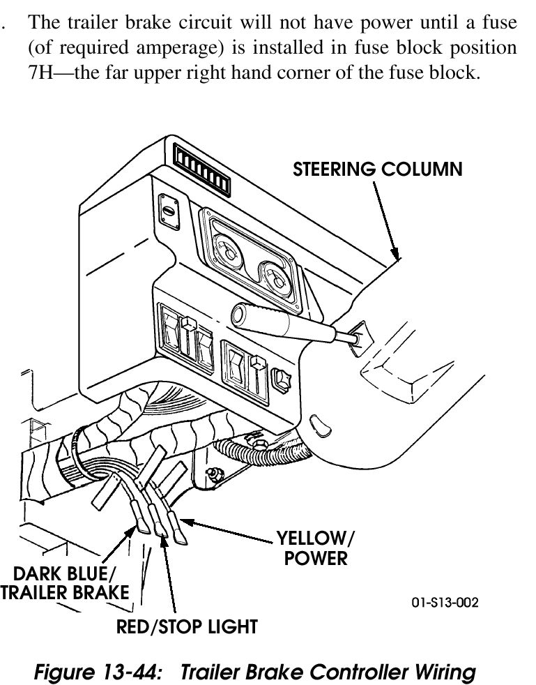
Electric Brake Controller

Tekonsha Trailer Brake Control 9030 Highskyrvparts Com
Tow Pro Technical Bulletin

Installation Instructions For Tekonsha Voyager Brake Controller Etrailer Com

How To Set The Tekonsha Voyager Electric Brake Controller

Tekonsha 3034 P Trailer Brake Controller Harness Compatible With Ford Econoline Expedition F 250 Super Duty 350 450 550 Lincoln Navigator
Tekonsha Voyager Xp Wiring Diagram
A comprehensive guide to the tekonsha voyager xp wiring diagram, understanding the main components of the tekonsha voyager xp wiring diagram, important safety considerations for installing the tekonsha voyager xp wiring diagram.
- Ensure that the power source is rated at least 8 amps.
- Use the proper gauge wires and terminals.
- Disconnect the negative terminal of the battery before making any connections.
- Check the wires and terminals for any signs of corrosion.
- Secure all connections with electrical tape or a heat shrink tube.
The Benefits of Installing the Tekonsha Voyager XP Wiring Diagram

Tekonsha 2 Plug Adapters

Tekonsha 9030 Voyager Trailer Brake Controller Proportional 1 To 4 Axles
Trailer Brake Controller Oem Wiring Ford Truck Enthusiasts Forums

How To Install A Tekonsha Brake Controller

Voyager Electric Brake Controller Clearance

Billavista Com Atv Tech Article By

Wiring Diagram Tekonsha Voyager Brake Controller 39510 Etrailer Com

Compare Tekonsha Voyager Vs Primus Etrailer Com

Trailer Brake Control For 14 19 Chevy Silverado Gmc Sierra

How To Set The Tekonsha Voyager Electric Brake Controller

Kirby Ch Wiring Brake Controllers

Tekonsha Voyager Trailer Brake Controller 1 To 4 Axles Proportional 39510

Tekonsha Voyager Trailer Brake Controller Installation 2014 Gmc Sierra 1500 Etrailer Com

Tekonsha 3035 Brake Control Wiring Adapter Com
JavaScript seems to be disabled in your browser. For the best experience on our site, be sure to turn on Javascript in your browser.
- My Purchase Orders
- Compare Products

Trailer Brake Controller Installation How-To

Just 5 Steps to Install Brake Controller and Wiring!
Installing a brake controller involves disconnecting the vehicle battery, mounting the brake controller onto dash and plugging the unit in with a vehicle-specific wiring harness. If your vehicle is not equipped with a plug-and-play harness, you can also splice in wiring for connecting a brake controller.
In this guide, we cover step-by-step how to install a brake controller. Remember to follow the specific instructions included with your unit -- find CURT instructions by part number .
- Disconnect the vehicle's negative battery cable
- Determine where to mount the controller on the dash
- Drill mounting holes for the bracket
- Fasten the brake controller into place
- Plug in the brake controller with a custom wiring harness
Want a brake controller with no installation? Check out Echo™
How to install a trailer brake controller video
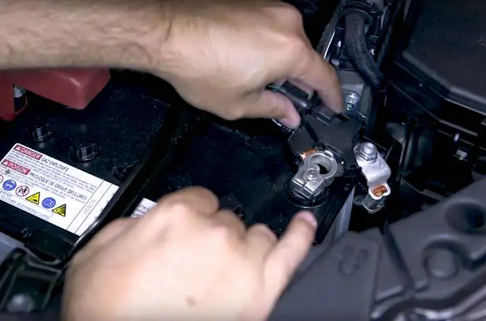
Step 1: Disconnect the negative battery cable
Any time you work on your vehicle’s electrical systems, it is a good idea to disconnect the battery. This is true when installing a brake controller as well. Disconnecting the battery helps prevent personal injury and damage to your vehicle’s electronics.
For a brake controller install, simply unbolt the negative battery cable and move it off to the side.
Step 2: Determine where to mount the controller
Find a suitable mounting location for the brake controller. On most vehicles, particularly large trucks and SUVs, the best place tends to be below and off to the side of the steering wheel. Here the controller will be easily visible but out of the way. It can also be mounted above the dash.
If you have a CB radio or other RF transmitter, make sure the brake controller is not installed close to these sensitive electronics.

Step 3: Drill mounting holes
With the brake controller positioned in the desired location, use the mounting bracket as a template to mark where you’ll need to drill. Then, drill a hole for each of the fasteners included with the bracket.
Be mindful of what you’re drilling into!
You don’t want to damage vehicle electronics behind the dash. If possible, remove the panel that you’re drilling into to avoid unnecessary risks.


Step 4: Fasten the brake controller into place
With the holes drilled, reposition the brake controller bracket and install the fasteners included with the unit. Many brake controllers come with self-tapping screws. When tightening the screws, be careful not to overtighten or strip out the holes.
Next, attach the brake controller to the bracket using the included bolts.

Step 5: Plug in the brake controller
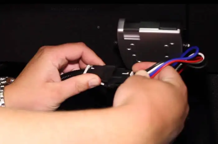
Using a vehicle-specific wiring harness, plug the brake controller into the vehicle. One end of the wiring harness plugs into the vehicle’s factory harness under the dash, and the other end plugs into the brake controller.
The location of your vehicle’s factory wiring harness may vary. Refer to the diagram below to locate yours.
Brake controller wiring locations
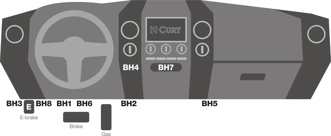
BH1 - Under dash, left of steering column, near emergency brake pedal
BH2 - Under dash, near center console
BH3 - Under dash, in junction box left of steering column
BH4 - Behind storage pocket, above ashtray
BH5 - Under dash, behind center access panel on passenger side
BH6 - Under dash, near brake pedal
BH7 - Behind storage pocket in center of dash
BH8 - Under dash, to right of emergency brake pedal

How to Wire a Brake Controller: Splice-in Option
If vehicle-specific brake controller wiring isn’t available for your vehicle, you may need to splice in a connection. You can do this using the CURT splice-in wiring harness #51515 .
If you prefer not to splice in wiring, you may wish to purchase the CURT Echo® brake controller – a wireless unit that Bluetooth® connects to your smartphone. To install the Echo®, all you need is a 7-way RV blade with 12+ volts power.
How to wire in trailer brake controller video

Step 1: Disconnect the vehicle’s battery
Start your splice-in brake controller installation by disconnecting the negative battery cable. This will help ensure your safety while working on the wiring system. It will also help protect your vehicle’s electrical components from damage.
Disconnect the negative cable, and move it to the side.
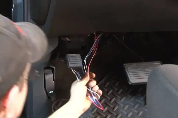
Step 2: Locate the brake controller wiring
Even if your vehicle doesn’t have a factory connector for plugging in a brake controller, it should have blunt-cut brake controller wiring, if it is compatible with a brake controller. This wiring bundle will be located somewhere underneath the dash.
Carefully separate the bundle of wires and remove any tape holding the wires together.
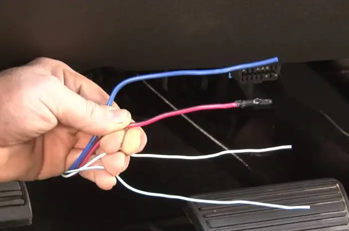
Step 3: Determine wiring connections
Strip the vehicle-side wires as needed and separate them out to prepare for splicing in the brake controller harness.
Note the following wire functions:
- Blue - Brake output to trailer
- Red - 12+ volt
- White - Ground
- White with blue stripe - Stop lights
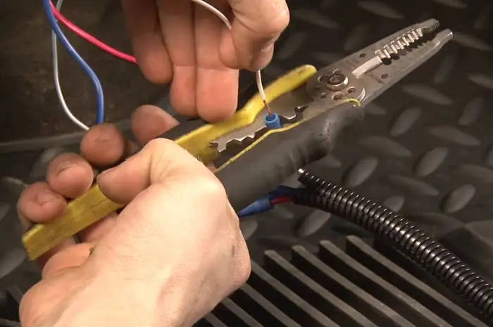
Step 4: Splice color-coded wires together
Strip the wires on the brake controller harness if needed (#51515). Then, attach butt connectors. Splice the wires from the vehicle to the brake controller harness, matching the colors as follows:
- Blue vehicle wire to blue brake controller wire
- Red 12+ volt vehicle wire to black brake controller wire
- White vehicle wire to white brake controller wire
- White with blue stripe vehicle wire to red brake controller wire

Step 5: Insert the quick plug and mount the brake controller
With the wires securely crimped together, you can now plug the brake controller harness into your brake controller unit.
Find a suitable mounting location for the brake controller and install it with the included bracket and other hardware. Make sure the brake controller is easily visible while driving but not obstructing your view of the road or other controls.

Step 6: Attach power wire to the battery
The final step is to supply power to your brake controller unit. This is done using a factory power feed wire already installed on the vehicle.
Locate the power feed wire under the hood, near the fuse box, and attach it to the auxiliary power terminal on your vehicle’s fuse box.
Finally, reconnect the negative battery cable.
Voyager Trailer Brake Controller Wiring Diagram
Tips on how to properly install a voyager trailer brake controller wiring diagram, check the wiring size and quality, check the power outputs, install connectors, check the settings.

Billavista Com Atv Tech Article By

Tekonsha 9030 Voyager Electric Brake Control 1 4 Trailer Axles Anythingtruck Com Truck Parts And Accessories Warehouse

Tekonsha 9030 Voyager Brake Activator Wiring Etrailer Com

I Have A 2010 Chevy 3500 With An Integrated Brake Controller Am Getting Service Trailer Message Where Do

Tekonsha P3 Proportional Brake Controller Rveethereyet

Billavista Com Trailer Brake Controller Tech Article By

Clam S Trailer Brake Control For 12 20 Ford Flex Lincoln

Tekonsha Brake Control Wiring Adapter W 2 Plug With Harness For Acura Controllers 3028
Tow Pro Technical Bulletin

Tekonsha Tk 9030 Voyager Brake Controller

Tekonsha Voyager Brake Controller Activating When I Turn On Headlights Etrailer Com

Voyager Brake Controller U Haul

Wiring Diagram Tekonsha Voyager Brake Controller 39510 Etrailer Com

Brake Controller Installation Starting From Scratch Etrailer Com

2011 F150 Electric Trailer Brake Help Ford Forum Community Of Truck Fans

IMAGES
VIDEO
COMMENTS
Learn how to install, level, and adjust the Voyager Brake Control for 2, 4, 6 and 8 brake applications. Follow the step-by-step guide and troubleshooting chart for optimal trailer braking performance.
Find out how to wire a Tekonsha Voyager brake controller for your trailer and vehicle. See a diagram of the basic connections, a link to the installation and wiring instructions, and expert answers to common questions.
Learn how to wire the Tekonsha Voyager brake controller for your vehicle and trailer. Find the wiring diagram, circuit breaker, installation kit and other products referenced in this question.
Find a basic wiring diagram and installation instructions for Tekonsha Voyager brake controller # 39510. Learn how to ground, connect and tap the wires for your vehicle and trailer.
Summary of Contents for Tekonsha Electronic Brake Control. Page 1 Electronic Brake Control Installation Guide Leveling the Sensor If trailer brakes lock up: Turn power down using power knob. For 2, 4, 6* and 8* brake applications After the brake control has been securely mounted WARNING The Brake Control must be mount- (Rotate power knob toward ...
One popular brake controller on the market is the Voyager brake controller. This article will guide you through the step-by-step process of installing and wiring a Voyager brake controller in your vehicle. Whether you are a DIY enthusiast or a novice, this complete diagram guide will help you navigate the installation process with ease.
This control specfically designed for use with electric trailer brakes. For Technical Assistance and Warranty Information call: 1-888-785-5832 or www.tekonsha.com. P/N 3840 REV J 08/03.
The wiring diagram for the Voyager Brake Controller includes several components, such as the brake controller itself, a brake switch, a battery, and the trailer brakes. The brake controller is typically connected to the vehicle's brake light switch, which triggers the trailer brakes when the tow vehicle's brakes are applied.
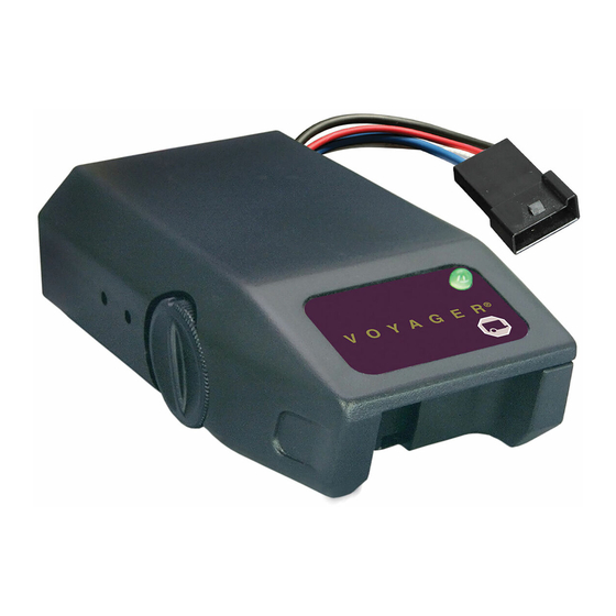
The Tekonsha 9030 is a versatile and easy-to-install electric brake controller that provides smooth and secure braking for trailers with 1-4 axles. It has a bi-colored LED indicator, a manual control lever, and a Plug & Play feature for quick connection with your vehicle's wiring.
But with the Tekonsha Voyager Brake Controller Wiring Diagram, you can make sure your braking system is running as smoothly as possible. This guide walks through every step of your brake controller installation, from selecting the right wires to connecting them to the… Read More » ... Tekonsha Voyager Trailer Brake Controller Installation ...
Learn how to install the Tekonsha Voyager XP brake controller for your trailer with this comprehensive guide. The wiring diagram shows the main power cable, breakaway switch, and brake controller components and their connections.
Tekonsha Voyager 9030 minimizes interference with tow vehicle electrical systems, uses a four wire hook up, has a broad setting range and is compatible with ...
Trailer Connector Brake Control Typical Wiring Diagram Vehicle Wiring WARNING Inadequate grounding may cause intermittent braking or lack sufficient voltage to trailer brakes and may result in accidents. 1. The WHITE wire must be connected to a suitable ground location. The negative terminal of the battery is a suitable ground location in
The wiring diagram is a visual representation of how the Tekonsha Voyager 9030 connects to your vehicle's electrical system and the trailer's braking system. It provides a clear and detailed guide on how to install and wire the controller correctly, ensuring optimal performance. By following the wiring diagram carefully, you can avoid any ...
Learn how to install a brake controller and a 7-way trailer connector on your vehicle with the ETBC7 kit. Follow the step-by-step instructions and diagrams for wiring, mounting and testing.
text black on colored background.Select Storable SettingsPress and hold the boost. button for 2 seconds until the "Select" menu comes up.Arrow down. o select the preferred "Trailer" setting and press OK. This "Trailer" setting is now ready to be cus-tomized by following the desired setting (Brake Type, Power Set.
Minimum wire gauges are as follows: 1-2 axle applications - 14 GA. 3-4 axle applications - 12 GA. 7. Collection of water inside the trailer connector mounted on the tow vehicle will reduce the life of the connector. 8. Technical Assistance Call Toll-Free: 1-888-785-5832 or www.tekonsha.com.
The connections you will need to make to install your Voyager brake controller are listed below. If your Voyager has a connector attached to the wires at the back you can use the Pigtail Wiring Harness, # 7894, to connect to the wires on the connector supplied by GM that is similar to the # 3015-S connector we carry.If you wanted a complete harness without splicing you could use the plug-in ...
Learn how to install a trailer brake controller in 5 easy steps with a vehicle-specific wiring harness or a splice-in option. Watch videos and view diagrams for different vehicle models and brake controller types.
BTT - Brake/Tail/Turn multiplexed wiring system* The vehicle's brake, tail & turn functions are combined on one wire. Yellow to vehicle Brake/Tail/Left Turn wire & Green to vehicle Brake/Tail/Right turn wire. Tail wire (brown) & Brake wire (red) are not used. TOW VEHICLE INPUTS - DETERMINATION: * Module may not work with some BTT wiring ...
The Voyager trailer brake controller wiring diagram is an important part of installing the brake system in your trailer. This diagram will show you exactly how to wire the system to ensure that it is properly connected and can function as intended. In addition to learning the correct wiring, there are some tips that you should keep in mind when ...
A proportional brake controller that activates trailer brakes in proportion to your vehicle's braking action. Features LED indicator, manual override, and adjustable gain and sensitivity. Includes bracket, hardware, and 5-year warranty.
Expert Reply: You should have four wires coming out of the back of your Tekonsha #9030 Voyager Brake Activator, part # 39510. They should be white, blue, red and black. The white wire is grounded. The red wire must tap into the cold side of your vehicle brakes. The blue wire will run to the trailer connector on the back of your vehicle.